Table of Contents
Advertisement
Quick Links
Advertisement
Table of Contents

Related Manuals for Schaeffler OPTIME Gateway 2


Summary of Contents for Schaeffler OPTIME Gateway 2
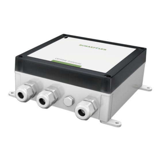
- Page 1 OPTIME Gateway 2 User manual...
-
Page 2: Table Of Contents
OPTIME GATEWAY 2 Contents OPTIME Gateway 2 ........................1 About the user manual ......................2 Signal words and symbols ....................2 Other symbols ........................3 Legal guidelines ........................ 3 Advice on third party products and services ..............3 General safety guidelines ..................... 4 ... -
Page 3: About The User Manual
UK Declaration of Conformity ..................41 About the user manual This user manual applies to the OPTIME Gateway 2 (called device in the following text). Signal words and symbols The warning and hazard symbols are defined in accordance with ANSI Z535.6-2011 In case of non-compliance, death or serious injury may occur. -
Page 4: Other Symbols
Wirepas, Wirepas Mesh and their logos are registered trademarks of Wirepas Ltd. The information given in this publication cannot be construed as constituting any related liability for products and services not produced or provided by Schaeffler Monitoring Services GmbH. Schaeffler Monitoring Services GmbH does not take ownership of these products and services. -
Page 5: General Safety Guidelines
All work may only be performed by a skilled person Usage not for the intended purpose The OPTIME Gateway 2 does not provide machine protection. It must not be used as a component of safety systems. The OPTIME Gateway 2 is not classified as a safety component in accordance with the EU Machine Directive 2006/42/EC. -
Page 6: Selection And Qualification Of Personnel
have read and understood this manual. If skilled personnel do not possess the necessary knowledge, they must be given the necessary training and instruction. Schaeffler can offer appropriate training courses on request. Work on electrical devices Work on electrical devices may only be carried out by a trained and skilled electrician. - Page 7 The device may only be installed by a trained and skilled electrician who observes the national and international regulations covering the installation of electro-technical equipment. Radio interference and electromagnetic interference Radio interference can be caused by any device that emits electromagnetic signals. With so many devices transmitting and receiving radio waves, interference can occur if radio waves are overlapping.
-
Page 8: Explosive Environments
The product can be connected with other devices, components or internal or external networks (e.g. internet) via each of these interfaces. Devices (like data carriers) connected via information interfaces may contain malware or execute malicious functions undetected. This product, or potentially your company infrastructure (e.g. IT infrastructure) can be damaged due to the use of these kinds of information interfaces. -
Page 9: Required Accessories
Any defects must be reported promptly as a complaint: Check the product immediately upon delivery for visible defects. Report any defects promptly as a complaint to Schaeffler. Description Structure The overall system consists of several components designed for condition monitoring and predictive maintenance: ... -
Page 10: Planning
Registering the OPTIME dashboard To configure the gateway and sensors it is necessary to register in the Schaeffler IoT Hub, so that sensors and gateways are automatically associated with your company. You can configure the components of your system, i.e. gateway and sensors, for your system tree. -
Page 11: Gateway Connections And Indicators
This user is able to create additional users. All created users will receive their login data by e-mail. To log into the OPTIME customer portal, please visit the following website: https://schaeffler-optime.com/dashboard Gateway connections and indicators The gateway is equipped with three cable glands for feeding through the cable to the power supply and optionally the cables for network connection or external antennas. -
Page 12: Install Gateway
Install gateway The gateway is mounted in a protective housing suitable for wall or ceiling installation. It can also be installed outdoors due to its protection type and UV resistance. The gateway is the core of the mesh network; it is recommended to install it prior to any OPTIME sensor. - Page 13 Figure 2 Installation location for the gateway Installation brackets are supplied with the gateway. NOTICE Suitable fixing material is included in the scope of delivery. If you use own fixing materials, please ensure that the screws have a minimum length of 40 Install the gateway to the selected location using the installation brackets.
-
Page 14: Electrical Connections
Electrical connections WARNING Only a qualified and skilled electrician is allowed to open the gateway’s housing, to install and commission the gateway and to connect the mains voltage or exchange the fuse or battery. WARNING Failure to adhere to the safety regulations can cause a life-threatening electric shock. - Page 15 8. Main power supply (AC power supply) 9. Fuse Figure 5 Gateway with the cover opened 2 1. LTE antennas 2. Backup battery (RTC) 3. Combined antenna (Bluetooth, Wi-Fi) 4. SMA connectors (LTE) To connect the electrical connections: 1. Open the cover of the gateway. Figure 6 Opening the cover of the gateway...
- Page 16 If the cellular connection is used (factory setting), a SIM card needs to be placed into the SIM card holder. The SIM card is either provided by Schaeffler or the customer. Then the gateway connects automatically with the Schaeffler cloud. It may take several minutes to establish the connection.
-
Page 17: Changing The Sim Card
The main function of the gateway is to transfer data between the sensor mesh network and the OPTIME backend. Various interfaces are available for communication between the gateway and Schaeffler cloud. Cellular communication is used by default. The following communication options are available: ... -
Page 18: Led Operation Modes And Status Indication
LED operation modes and status indication The gateway has 2 LED indicators that show various statuses depending on the operating mode. Figure 10 LED indicators 1. LED 2 2. LED 1 There are two operating modes: In operation mode ... -
Page 19: In Operation Mode
Figure 11 LED operation modes and status indication In operation mode When the gateway is in the operation mode, the LED indicators show the operating status. Table 1 Operating mode LED indicators LED2 LED1 Function Green light A connection between the gateway and the OPTIME backend has been established. ... -
Page 20: Status Indication For Gateway Configuration
Table 2 Debug mode LED indicators LED2 LED1 Function Flashing green A good Internet connection Flashing yellow A bad Internet connection Flashing red No Internet connection Flashing pink 4G Internet connection Flashing blue 3G Internet connection Flashing yellow 2G Internet connection Status indication for gateway configuration NOTICE Access to the configuration UI is only available during start-up of the gateway. -
Page 21: Gateway Configuration
Login to gateway configuration UI Before you start, you need a Wi-Fi password. 1. To get the Wi-Fi password, start the Schaeffler OPTIME mobile app on your mobile device and log in. 2. On the start page, select the [ Menu ] icon in the top left corner. - Page 22 3. Select [ Scan device ] from the Menu. 4. Select [ Scan gateway ]. The QR code scanner opens. 5. Select [ Scan QR code ].
- Page 23 The camera opens. 6. Scan the QR code on the nameplate of the gateway. As a result, you receive the Wi-Fi password and other information on the gateway. 7. Copy the Wi-Fi password.
- Page 24 To access the gateway configuration user interface (UI) using a browser in a mobile device or a computer: Switch on the gateway and wait until the LED indicator is blue. 2. While the LED indicator is blue, press the [ Push ] button on the gateway. A green LED flashes to acknowledge that the [ Push ] button was pressed.
-
Page 25: Gateway Configuration Ui
Enter the Wi-Fi password and press [ Next ]: For details on the UI, see Gateway configuration UI, on page 24. You can now change the configuration. For details, see Configure gateway settings, page 29. The connection ends after 10 minutes of inactivity, or if the [ Exit ] icon is pressed. NOTICE The hotspot deactivates when you leave the configuration UI. - Page 26 Figure 12 Start page of the configuration UI: 1 Exit, 2 Settings, 3 Language selection, 4 Network status, 5 Device configuration, 6 Support data, 7 Home Designation Description (1) Exit Exit the configuration session. The Wi-Fi access point will no longer be accessible until the next reboot.
- Page 27 (6) Support data Download log files and view the license information. (7) Home Press the Schaeffler logo to return to the status page. Network status The Network status section shows the status of the communication interface between the gateway and cloud.
- Page 28 Green line: Connected. Red line: Disconnected. NOTICE If the connection was established (green line) but later the Internet connection was lost, the colour of the line does not change back to red. Figure 14 Network status, connection status: Disconnected...
- Page 29 Device configuration The Device configuration section shows the current gateway settings. Figure 15 Device configuration data To download the gateway configuration data in .txt format, press [ Download ].
-
Page 30: Configure Gateway Settings
Support data In the Support data section you can: Download log files, for example, to be delivered to the Schaeffler support team. View the licence information. 1. Press [ Download ] to download a .zip file that contains the encrypted log files. - Page 31 Figure 16 Gateway settings icons Designation Description Cellular icon Opens the cellular (SIM) settings. Ethernet (LAN) icon Opens the LAN settings. If the gateway is to be connected with a local network via the RJ45 port provided in the device, the necessary settings can be done here.
- Page 32 Figure 17 Configure SIM settings 3. If you need to add a specific provider, then disable the [ Select operator automatically ] selection and select the operator manually from the [ Operator ] list. 4. To avoid roaming charges abroad, disable the [ Roaming ] selection. 5.
- Page 33 Figure 18 Ethernet (LAN) settings 2. Enable/disable DHCP. It is recommended to keep DHCP enabled. If you disable DHCP, enter the IP address of the network, the network prefix and the IP address of the gateway. 3. Enter the DNS server address, if needed. 4.
- Page 34 Figure 19 Configure Wi-Fi 2. Enable/disable the Wi-Fi settings. Figure 20 Wi-Fi settings...
- Page 35 3. Change the Wi-Fi settings as needed: Designation Description Network name (SSID) Enter the name of the network. Password Password to the selected network. Enable DHCP Enable/disable DHCP. It is recommended to keep DHCP enabled. If you disable DHCP, enter the IP address of the network, the network prefix and the IP address of the gateway.
-
Page 36: Change The Language Of The Ui
Figure 22 Time zone selection 5. Press [ Apply ] to save the changes to the configuration. Change the language of the UI To change the language of the gateway configuration UI 1. Press the [ Language selection ] icon and select the language from the list. The language of the UI changes immediately. -
Page 37: Exit The Configuration Session
The gateway may only be returned following consultation with Schaeffler. It is imperative that the gateway is deactivated for return shipment. If there is a battery fault, shipping of the device is not... -
Page 38: Cleaning
and battery must be properly disposed of on site in accordance with the national disposal regulations. Cleaning You can clean the outside of the gateway housing if necessary. Disconnect the gateway from the mains before cleaning. Clean the gateway housing using a soft, lint-free cloth. ... - Page 39 Electrical characteristics Protection class Power consumption Power supply AC 100 to 240 Frequency 50/60 Power supply DC 10,8 to 13,2 Fuse 250 VAC, 1,25 A, 1500 VAC interrupt. rating certified in UL category JDYX2 Backup battery for RTC Lithium 3,0 VDC, 10 mA max.
-
Page 40: Gateways Dimensions
Gateways dimensions Figure 25 Gateway dimensions... -
Page 41: Appendix
Appendix EU Declaration of Conformity... -
Page 42: Uk Declaration Of Conformity
UK Declaration of Conformity... - Page 43 All information has been carefully compiled and checked by us, but we cannot guarantee complete accuracy. We reserve the right to make corrections. Therefore, please always check whether more up‐to‐date or amended information is available. This publication supersedes all deviating information Schaeffler Monitoring Services GmbH from older publications. Printing, including Kaiserstraße 100 excerpts, is only permitted with our approval. 52134 Herzogenrath © Schaeffler Monitoring Services GmbH Germany GW2 / 01 / en‐GB / DE / 2023‐04‐17 www.schaeffler.de/optime ...
Need help?
Do you have a question about the OPTIME Gateway 2 and is the answer not in the manual?
Questions and answers