Tektronix P6248 Service Manual
1.7 ghz (typical) differential probe
Hide thumbs
Also See for P6248:
- Service manual (58 pages) ,
- Instructions manual (40 pages) ,
- Instructions manual (188 pages)

Subscribe to Our Youtube Channel
Related Manuals for Tektronix P6248


Summary of Contents for Tektronix P6248
- Page 1 P6248 1.7 GHz (Typical) Differential Probe Service Manual *P071057304* 071-0573-04...
- Page 3 P6248 1.7 GHz (Typical) Differential Probe Service Manual Warning The servicing instructions are for use by qualified personnel only. To avoid personal injury, do not perform any servicing unless you are qualified to do so. Refer to all safety summaries prior to performing service.
- Page 4 Copyright © Tektronix. All rights reserved. Licensed software products are owned by Tektronix or its subsidiaries or suppliers, and are protected by national copyright laws and international treaty provisions. Tektronix products are covered by U.S. and foreign patents, issued and pending. Information in this publication supersedes that in all previously published material.
- Page 5 Tektronix, with shipping charges prepaid. Tektronix shall pay for the return of the product to Customer if the shipment is to a location within the country in which the Tektronix service center is located. Customer shall be responsible for paying all shipping charges, duties, taxes, and any other charges for products returned to any other locations.
-
Page 7: Table Of Contents
Maintenance......................Cleaning ....................... Replacing TEKPROBE Interface Pins ..............Removing and Replacing the TEKPROBE Interface Collar..........Options......................Replaceable Parts ....................Appendix A: Alternate Verification Procedures ..............Equipment Required..................Preparation..................... CMRR (Common-Mode Rejection Ratio) ..............P6248 1.7 GHz Differential Probe Service Manual... - Page 8 Figure 14: Replacing the TEKPROBE collar ..............Figure 15: P6248 replaceable parts................Figure 16: P6248 standard accessories................Figure 17: P6248 optional accessories ................Figure 18: Normalizing the setup................Figure 19: Setup for the CMRR tests ................P6248 1.7 GHz Differential Probe Service Manual...
-
Page 9: General Safety Summary
Do Not Operate in an Explosive Atmosphere. Keep Product Surfaces Clean and Dry. Provide Proper Ventilation. Refer to the manual’s installation instructions for details on installing the product so it has proper ventilation. P6248 1.7 GHz Differential Probe Service Manual... - Page 10 DANGER indicates an injury hazard immediately accessible as you read the marking. WARNING indicates an injury hazard not immediately accessible as you read the marking. CAUTION indicates a hazard to property including the product. The following symbol(s) may appear on the product: P6248 1.7 GHz Differential Probe Service Manual...
-
Page 11: Service Safety Summary
Use Care When Servicing With Power On. Dangerous voltages or currents may exist in this product. Disconnect power, remove battery (if applicable), and disconnect test leads before removing protective panels, soldering, or replacing components. To avoid electric shock, do not touch exposed connections. P6248 1.7 GHz Differential Probe Service Manual... - Page 12 Service Safety Summary P6248 1.7 GHz Differential Probe Service Manual...
-
Page 13: Preface
Preface This manual contains specifications and service information for the P6248 differential probe. Related Manuals For operating information, refer to the P6248 Instructions (071-0566-XX). P6248 1.7 GHz Differential Probe Service Manual... - Page 14 Preface viii P6248 1.7 GHz Differential Probe Service Manual...
-
Page 15: Specifications
Specifications The specifications in the following tables apply to a P6248 differential probe installed on a Tektronix TDS694C oscilloscope. When the probe is used with another oscilloscope, the oscilloscope must have an input impedance of 50 Ω. The probe must have a warm-up period of at least 20 minutes and be in an environment that does not exceed the limits described in the environmental specifications... -
Page 16: Typical Characteristics
≤ ±0.5 dB to 850 MHz (deviation from a nominal slope) Bandwidth (probe only) DC to ≥1.7 GHz (- 3dB) @ ≤27 ºC (÷1 range) DC to ≥1.85 GHz (- 3dB) @ ≤27 ºC (÷10 range) <265 ps Rise time (probe and oscilloscope) P6248 1.7 GHz Differential Probe Service Manual... -
Page 17: Figure 1: Typical Common-Mode Rejection Ratio (÷1 And ÷10 Attenuation)
Specifications Figure 1: Typical Common-Mode Rejection Ratio (÷1 and ÷10 attenuation) Figure 2: Typical differential input impedance versus frequency P6248 1.7 GHz Differential Probe Service Manual... -
Page 18: Nominal Characteristics
(See Table 4.) Table 4: Nominal electrical characteristics Characteristic Description Input configuration Differential (two inputs, + and - ), with case ground Output coupling Attenuation settings ÷1 and ÷10 Termination Terminate output into 50 Ω P6248 1.7 GHz Differential Probe Service Manual... -
Page 19: Performance Verification
Performance Verification Use the following procedures to verify the warranted specifications of the P6248 Differential Probe. Before beginning these procedures, photocopy the test record and use it to record the performance test results. The recommended calibration interval is one year. -
Page 20: Preparation
6. Allow the probe and test equipment to warm up for 20 minutes at an ambient temperature of 20 ºC to 30 ºC (68 ºF to 86 ºF). Perform the verification procedures in order. P6248 1.7 GHz Differential Probe Service Manual... -
Page 21: Output Offset Voltage
3. Verify that the output voltage is ≤ ±10 mV. 4. Change the probe attenuation to ÷1. 5. Verify that the output voltage is ≤ ±10 mV. 6. Keep the output connections for the next procedure. P6248 1.7 GHz Differential Probe Service Manual... -
Page 22: Dc Attenuation Accuracy
14. Calculate the attenuation as follows: (V 1 - V 2) ÷ (V 1 - V 15. Verify that the attenuation is in the range of 0.98 to 1.02. 16. Keep the output connections for the next procedure. P6248 1.7 GHz Differential Probe Service Manual... -
Page 23: Differential Signal Range
÷ V 7. Verify that the attenuation is in the range of 9.5 to 10.5. 8. Remove the Y-lead adapter from the probe and reverse the connection (black to +, red to -). P6248 1.7 GHz Differential Probe Service Manual... - Page 24 19. Measure and record the output voltage as V 20. Calculate the attenuation as V ÷ V 21. Verify that the attenuation is in the range of 0.95 to 1.05. 22. Remove all connections. P6248 1.7 GHz Differential Probe Service Manual...
-
Page 25: Rise Time
) that you measured in step 6 represents the rise time of the test system without the probe. The system rise time is used to calculate the probe rise time (t ) in steps 22 and 31. Figure 6: Test system rise time setup P6248 1.7 GHz Differential Probe Service Manual... -
Page 26: Figure 7: Rise Time Setup For Test System With Probe
Observe proper polarity; the + side of the probe should be on the center square pin of the probe tip adapter. The test setup should now appear as shown. (See Figure 7.) Figure 7: Rise time setup for test system with probe P6248 1.7 GHz Differential Probe Service Manual... - Page 27 10% and 90% amplitude points on the waveform. Record the rise time for ÷10 as t s+p. 31. Calculate the probe rise time using the following formula: 32. Record the calculated probe rise time for ÷10 on the test record. P6248 1.7 GHz Differential Probe Service Manual...
-
Page 28: Common-Mode Rejection Ratio
6. Attach the cable from port 2 to the 1103 channel 1 output connector (conventional BNC). Use a male BNC adapter, if necessary. 7. Normalize the network analyzer to remove the loss through channel 1 of the 1103 power supply. P6248 1.7 GHz Differential Probe Service Manual... -
Page 29: Figure 8: Setup For Cmrr Test
Do not allow kinks, loops or other deformities in the probe cable, and maintain a maximum distance between the probe head and the probe control box. P6248 1.7 GHz Differential Probe Service Manual... - Page 30 48 dB). The calculation has been performed in the ÷10 Measured Feedthrough column. 14. Verify that the feedthrough is less than the values in ÷10 Measured Feedthrough column of the table. (See Table 6.) P6248 1.7 GHz Differential Probe Service Manual...
-
Page 31: Tekprobe Communication (Operational Check)
12. Verify that the channel 1 scale factor is 1 V/div. 13. Set the probe attenuation to ÷1. 14. Verify that the channel 1 scale factor is 100 mV/div. This completes the functional check and the performance verification. P6248 1.7 GHz Differential Probe Service Manual... - Page 32 _____________ 1 GHz -30 dB _____________ _____________ ÷10 setting 1 MHz -65 dB _____________ _____________ 100 MHz -45 dB _____________ _____________ 500 MHz -40 dB _____________ _____________ 1 GHz -38 dB _____________ _____________ P6248 1.7 GHz Differential Probe Service Manual...
-
Page 33: Adjustment Procedures
, Separate Trigger (Square and sine wave pk-pk or Sync output output) 50 Ω terminator 50 Ω ± 1 Ω Tektronix part number 011-0049-01 (needed only if oscilloscope does not support 50 Ω termination) P6248 1.7 GHz Differential Probe Service Manual... -
Page 34: Adjustment Locations
Adjustment Procedures Adjustment locations The location of the adjustments inside the control box are shown below. Figure 9: Adjustment locations P6248 1.7 GHz Differential Probe Service Manual... -
Page 35: Offset (Preliminary)
4. Adjust the ÷1 offset adjustment for 0 mV, ±1 mV. 5. Change the probe attenuation to ÷10. 6. Adjust the ÷10 offset adjustment for 0 mV, ±1 mV. 7. Keep the output cable set up for the next step. P6248 1.7 GHz Differential Probe Service Manual... -
Page 36: Gain
4. Set the probe to ÷1 attenuation. 5. Adjust the power supply to output about 700 mV. 6. Adjust the ÷1 gain adjustment until the output voltage measures the same as the input within ±5 mV. P6248 1.7 GHz Differential Probe Service Manual... -
Page 37: Offset (Final)
11. Keep the probe output connections for the next step. Offset (Final) NOTE. The offset and gain adjustments interact. 1. Repeat steps 1 through 6 of the Offset (preliminary) procedure. 2. Remove the output cable termination and input for the next procedure. P6248 1.7 GHz Differential Probe Service Manual... -
Page 38: Dc Cmrr
2. Connect a second BNC cable from the function generator Trigger or Sync Output to the External Trigger or Channel 2 input of the oscilloscope. Figure 12: Setup for DC CMRR and AC CMRR adjustments 3. Set the probe to ÷1 attenuation. P6248 1.7 GHz Differential Probe Service Manual... - Page 39 10. Adjust the ÷10 DC CMRR for minimum amplitude in the flat portions of the displayed waveform. This adjustment does not affect the leading edge transitions. 11. Keep the connections for the next procedure. P6248 1.7 GHz Differential Probe Service Manual...
-
Page 40: Ac Cmrr
Repeat the DC CMRR adjustment steps 5 through 12. 10. Remove all connections from the probe. Carefully replace the top cover of the control box and the four retaining screws. This completes the adjustment procedures. P6248 1.7 GHz Differential Probe Service Manual... -
Page 41: Maintenance
(See Figure 13.) 2. To replace the pin, insert the new pin into the socket and press it in against a hard surface. Figure 13: Replacing TEKPROBE interface pins P6248 1.7 GHz Differential Probe Service Manual... -
Page 42: Removing And Replacing The Tekprobe Interface Collar
2. To replace the collar, align the smaller group of pins with the smaller of the two holes in the interface collar and align the tabs with the slots. Gently press the two pieces together. (See Figure 14.) Figure 14: Replacing the TEKPROBE collar P6248 1.7 GHz Differential Probe Service Manual... -
Page 43: Options
Options Option 95 is a report of the calibration data. This option must be ordered at the time of purchase. P6248 1.7 GHz Differential Probe Service Manual... - Page 44 Options P6248 1.7 GHz Differential Probe Service Manual...
-
Page 45: Replaceable Parts
Replaceable Parts Figure 15: P6248 replaceable parts Table 9: P6248 Probe replaceable parts list Fig. & Tektronix Serial Serial index part number number effective discont’d Qty Name & description 15-1 010-6248-00 PROBE,DIFF,ACT:1.7GHZ DIFFERENTIAL,CERTIFICATE OF TRACEABLE CALIBRATION STANDARD,P6248 211-0001-00 SCREW,MACHINE:2-56 X 0.25,PNH,STL CD PL,POZ... -
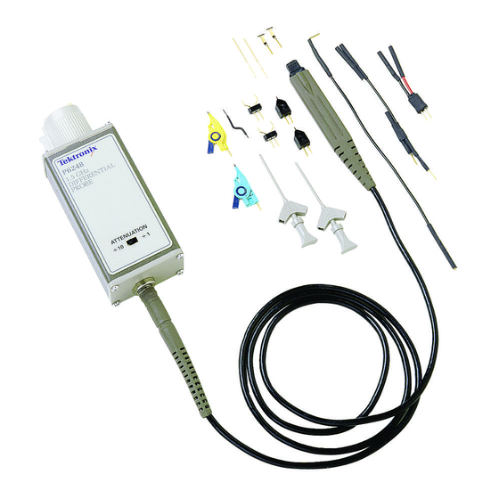
Page 46: Figure 16: P6248 Standard Accessories
Replaceable Parts Figure 16: P6248 standard accessories P6248 1.7 GHz Differential Probe Service Manual... - Page 47 Serial index Tektronix part number number effective discont’d Name & description 16-1 020-2702-02 ACCESSORY PKG, P6248 (Includes items 2 through 10) 196-3434-00 Y LEAD ADAPTER 196-3504-XX SOLDER-DOWN LEAD, 1 INCH 196-3505-00 SOLDER-DOWN LEAD, 3 INCH 196-3437-XX GROUND LEAD 016-1781-00 ACCESSORY KIT: TIP SAVER, PKG OF 2...
-
Page 48: Figure 17: P6248 Optional Accessories
Replaceable Parts Figure 17: P6248 optional accessories P6248 1.7 GHz Differential Probe Service Manual... - Page 49 ADJUSTMENT TOOL: 5 INCH TOTAL, PLASTIC,W/PLASTIC TIP ONE END METAL TIP OPPOSITE END 011-0049-01 TERMN,COAXIAL:50 OHM,2W,BNC 1103 1103 TEKPROBE POWER SUPPLY 012-0076-00 CA ASSY,RF:COAXIAL,RFD,50 OHM,20 L,BNC, MALE,STR,BOTH ENDS,W/STRAIN RELIEF BOOT BOTH ENDS 679-5027-00 CKT BD SUBASSY:1394 ADAPTER P6248 1.7 GHz Differential Probe Service Manual...
- Page 50 Replaceable Parts P6248 1.7 GHz Differential Probe Service Manual...
-
Page 51: Appendix A: Alternate Verification Procedures
Tektronix Type 1103 Tektronix Type 1103 BNC-to-Type-N coax Type N-male-to-BNC female Tektronix part number adapters (2) 103-0045-00 Tektronix part number BNC cables (2) 50 Ω, 18 inch 012-0076-00 Tektronix part number BNC-to-probe tip adapter 679-4094-00 P6248 1.7 GHz Differential Probe Service Manual... -
Page 52: Preparation
Adjust the spectrum analyzer input attenuator to accept the high level of 10 dBm. d. Set the reference level to 10 dBm, the center frequency to 1 MHz, and the vertical scale to 10 dB/div. P6248 1.7 GHz Differential Probe Service Manual... -
Page 53: Figure 19: Setup For The Cmrr Tests
floor. Verify that the change in the level (relative to the level recorded in step 1 f above) is less than or equal to the ÷1 measured feed through column of the table. (See Table 13 on page 41.) P6248 1.7 GHz Differential Probe Service Manual... - Page 54 Carefully dress the probe cable so that it does not cross itself or pass near the BNC to probe tip adapter. Improperly dressing the probe cable can affect the measurements at 1 GHz and above. 22. Repeat steps 10 through 16. P6248 1.7 GHz Differential Probe Service Manual...
- Page 55 ≤-60 dBm ≤-65 dBm 100 MHz ≥38 dB ≥25 dB ≤-38 dBm ≤-45 dBm 500 MHz ≥35 dB ≥20 dB ≤-35 dBm ≤-40 dBm 1 GHz ≥30 dB ≥18 dB ≤-30 dBm ≤-38 dBm P6248 1.7 GHz Differential Probe Service Manual...
Need help?
Do you have a question about the P6248 and is the answer not in the manual?
Questions and answers