Sign In
Upload
Manuals
Brands
Tektronix Manuals
Measuring Instruments
P6248
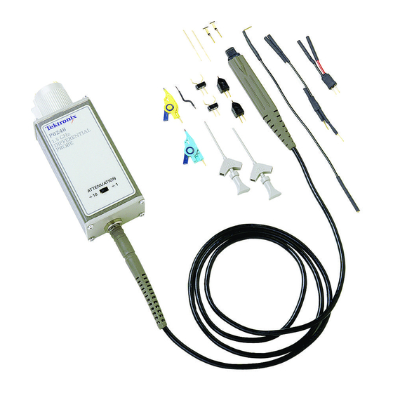
Tektronix P6248 Manuals
Manuals and User Guides for Tektronix P6248. We have
5
Tektronix P6248 manuals available for free PDF download: Instructions Manual, Service Manual
Tektronix P6248 Instructions Manual (188 pages)
400 MHz & 1GHz Differential Probes
Brand:
Tektronix
| Category:
Test Equipment
| Size: 7.56 MB
Table of Contents
English
6
Table of Contents
6
Related Manuals
8
Preface
8
Contacting Tektronix
9
Getting Started
12
Features and Accessories
12
Installation
17
Instruments with the Tekprobe II Interface (Tektronix TDS 400, 500, 600, and 700 Series Oscilloscopes)
18
Instruments Without the Tekprobe II Interface
18
Maximum Input Voltage
19
Common-Mode Signal Range
19
Input Voltage Limits
19
Operating Basics
19
Differential-Mode Signal Range
20
Attenuation Settings
20
DC Reject
20
Probe Grounding
21
Input Impedance and Probe Loading
22
Common-Mode Rejection
23
Probing Techniques to Maximize CMRR
24
Reference
25
Problems with Single-Ended Measurements
25
Differential Measurements
25
Common-Mode Rejection Ratio
26
Assessing CMRR Error
26
Input Impedance Effects on CMRR
27
Extending the Input Leads
27
Extending the Probe Output
28
Terminating the Probe
28
Extending the Ground Lead
28
Effect of Extending the Output Cable
29
Using the Probe with Other Instruments
29
Français
40
Consignes de Sécurité
42
Manuels Associés
44
Préface
44
Pour Contacter Tektronix
45
Caractéristiques et Accessoires
46
Mise en Route
46
Installation
53
Instruments Dotés de L'interface Tekprobe II (Oscilloscopes Tektronix TDS de la Série 400, 500, 600 et 700)
53
Instruments Sans L'interface Tekprobe II
53
Plage des Signaux en Mode Commun
55
Principes de Fonctionnement
55
Seuils de Tension D'entrée
55
Tension D'entrée Maximale
55
Plage des Signaux en Mode Différentiel
56
Réglages D'atténuation
56
Réjection CC
56
Mise à la Terre de la Sonde
57
Impédance D'entrée et Chargement de la Sonde
58
Réjection en Mode Commun
59
Techniques pour Optimiser le Taux de Réjection en Mode Commun (CMRR)
60
Mesures Différentielles
62
Problèmes Avec Mesures Sur Sorties Simples
62
Référence
62
Evaluation de L'erreur du Taux de Réjection en Mode Commun (CMRR)
63
Taux de Réjection en Mode Commun
63
Effets de L'impédance D'entrée Sur le Taux de Réjection en Mode Commun (CMRR)
64
Rallongement des Conducteurs D'entrée
64
Rallongement de la Sortie de la Sonde
65
Rallongement du Conducteur de Masse
65
Terminaison de la Sonde
65
Effet Provoqué Par le Rallongement du Câble de Sortie
66
Utilisation de la Sonde Avec D'autres Instruments
66
Caractéristiques Garanties
67
Spécifications
67
Caractéristiques Types
69
Caractéristiques Nominales
72
Deutsch
80
Zusammenfassende Sicherheitshinweise
82
Verwandte Handbücher
84
Vorwort
84
Wenn Sie sich mit Tektronix in Verbindung Setzen wollen
85
Merkmale und Zubehör
86
Zu Beginn
86
Der Serie TDS 400, 500, 600 und 700)
92
Geräte mit Schnittstelle Tekprobe II
92
Geräte ohne Schnittstelle Tekprobe II
92
Installation
92
Gleichtaktsignalbereich
94
Grenzwerte Eingangsspannung
94
Grundzüge der Betriebsweise
94
Maximale Eingangsspannung
94
DC-Sperrung
95
Differentialsignalbereich
95
Dämpfungseinstellungen
95
Tastkopferdung
96
Eingangsimpedanz und Tastkopfbelastung
97
Gleichtaktunterdrückung
98
Prüfverfahren zur Maximierung der Gleichtaktunterdrückung
99
Differentialmessungen
101
Probleme bei Eintaktmessungen
101
Referenzteil
101
Gleichtaktunterdrückungsverhältnis
102
Auswirkungen der Eingangsimpedanz auf das Gleichtaktunterdrückungsverhältnis
103
Bestimmung des Gleichtaktunterdrückungsfehlers
103
Verlängerung der Eingangsleitungen
103
Verlängerung der Erdleitung
104
Verlängerung des Tastkopfausgangs
104
Abschluß des Tastkopfs
105
Auswirkungen einer Verlängerung der Ausgangsleitung
105
Verwendung des Tastkopfs mit anderen Geräten
105
Advertisement
Tektronix P6248 Service Manual (58 pages)
1.7 GHz Typical Differential Probe
Brand:
Tektronix
| Category:
Measuring Instruments
| Size: 0.56 MB
Table of Contents
Table of Contents
5
General Safety Summary
7
Service Safety Summary
9
Preface
11
Related Manuals
11
Contacting Tektronix
11
Specifications
13
Warranted Characteristics
13
Typical Characteristics
14
Figure 1: Typical Common-Mode Rejection Ratio
15
Figure 2: Typical Differential Input Impedance Versus Frequency
15
Figure 3: Dimensions of Probe Head and Compensation Box
16
Nominal Characteristics
16
Performance Verification
17
Equipment Required
17
Preparation
18
Figure 4: Setup for the Output Offset Voltage Test
19
Output Offset Voltage
19
DC Attenuation Accuracy
20
Figure 5: Setup for Differential-Mode Tests
21
Differential Signal Range
21
Figure 6: Test System Rise Time Setup
23
Rise Time
23
Figure 7: Rise Time Setup for Test System with Probe
24
Common-Mode Rejection Ratio
26
Figure 8: Setup for CMRR Test
27
TEKPROBE Communication (Operational Check)
28
Adjustment Procedures
31
Equipment Required
31
Figure 9: Adjustment Locations
32
Figure 10: Setup for the Offset Adjustment
33
Offset (Preliminary)
33
Figure 11: Setup for Gain Adjustment
34
Gain
34
Offset (Final)
35
DC Cmrr
35
Figure 12: Setup for DC CMRR and AC CMRR Adjustments
36
Ac Cmrr
37
Figure 13: Replacing TEKPROBE Interface Pins
39
Maintenance
39
Cleaning
39
Replacing TEKPROBE Interface Pins
39
Figure 14: Replacing the TEKPROBE Collar
40
Removing and Replacing the TEKPROBE Interface Collar
40
Options
41
Figure 15: P6248 Replaceable Parts
43
Replaceable Parts
43
Figure 16: P6248 Standard Accessories
45
Figure 17: P6248 Optional Accessories
47
Appendix A: Alternate Verification Procedures
51
Equipment Required
51
Preparation
52
Figure 18: Normalizing the Setup
53
CMRR (Common-Mode Rejection Ratio)
53
Figure 19: Setup for the CMRR Tests
54
Tektronix P6248 Service Manual (55 pages)
1.7 GHz (Typical) Differential Probe
Brand:
Tektronix
| Category:
Measuring Instruments
| Size: 1 MB
Table of Contents
Table of Contents
7
General Safety Summary
9
Service Safety Summary
11
Preface
13
Related Manuals
13
Specifications
15
Warranted Characteristics
15
Typical Characteristics
16
Figure 1: Typical Common-Mode Rejection Ratio (÷1 and ÷10 Attenuation)
17
Figure 2: Typical Differential Input Impedance Versus Frequency
17
Nominal Characteristics
18
Figure 3: Dimensions of Probe Head and Compensation Box
18
Performance Verification
19
Equipment Required
19
Preparation
20
Output Offset Voltage
21
Figure 4: Setup for the Output Offset Voltage Test
21
DC Attenuation Accuracy
22
Differential Signal Range
23
Figure 5: Setup for Differential-Mode Tests
23
Rise Time
25
Figure 6: Test System Rise Time Setup
25
Figure 7: Rise Time Setup for Test System with Probe
26
Common-Mode Rejection Ratio
28
Figure 8: Setup for CMRR Test
29
TEKPROBE Communication (Operational Check)
31
Adjustment Procedures
33
Equipment Required
33
Adjustment Locations
34
Figure 9: Adjustment Locations
34
Offset (Preliminary)
35
Figure 10: Setup for the Offset Adjustment
35
Gain
36
Figure 11: Setup for Gain Adjustment
36
Offset (Final)
37
DC Cmrr
38
Figure 12: Setup for DC CMRR and AC CMRR Adjustments
38
Ac Cmrr
40
Maintenance
41
Cleaning
41
Replacing TEKPROBE Interface Pins
41
Figure 13: Replacing TEKPROBE Interface Pins
41
Removing and Replacing the TEKPROBE Interface Collar
42
Figure 14: Replacing the TEKPROBE Collar
42
Options
43
Replaceable Parts
45
Figure 15: P6248 Replaceable Parts
45
Figure 16: P6248 Standard Accessories
46
Figure 17: P6248 Optional Accessories
48
Appendix A: Alternate Verification Procedures
51
Equipment Required
51
Preparation
52
CMRR (Common-Mode Rejection Ratio)
52
Figure 18: Normalizing the Setup
52
Figure 19: Setup for the CMRR Tests
53
Advertisement
Tektronix P6248 Instructions Manual (39 pages)
1.7 GHz (Typical) Differential Probe
Brand:
Tektronix
| Category:
Test Equipment
| Size: 0.41 MB
Table of Contents
Table of Contents
5
General Safety Summary
7
Preface
9
Contacting Tektronix
10
Getting Started
11
Features and Accessories
11
Installation
18
Figure 1: Input Connector of TEKPROBE Interface
18
Instruments with the TEKPROBE Interface (Tektronix TDS 400, 500, 600, and 700 Series Oscilloscopes)
19
Instruments Without the TEKPROBE Interface
19
Operating Basics
21
Input Voltage Limits
21
Maximum Input Voltage
21
Common-Mode Signal Range
21
Differential-Mode Signal Range
22
Attenuation Settings
22
Probe Grounding
22
Figure 2: Using the Short Ground Contact
23
Input Impedance and Probe Loading
24
Figure 3: Typical Probe Input Model
24
Common-Mode Rejection
25
Probing Techniques to Maximize CMRR
25
Figure 4: Using the Input Lead Accessories to Achieve
25
Figure 5: Using the Twinfoot Adapter
26
Reference
27
Problems with Single-Ended Measurements
27
Differential Measurements
27
Common-Mode Rejection Ratio
28
Assessing CMRR Error
28
Figure 6: Simplified Model of a Differential Amplifier
28
Input Impedance Effects on CMRR
29
Extending the Input Leads
29
Extending the Ground Lead
30
Extending the Probe Output
30
Terminating the Probe
30
Figure 7: Twisting the Input Leads
30
Effect of Extending the Output Cable
31
Using the Probe with Other Instruments
31
Specifications
33
Warranted Characteristics
33
Typical Characteristics
35
Figure 8: Typical Common-Mode Rejection Ratio (B1 and B10 Attenuation)
36
Figure 9: Typical Differential Input Impedance Versus Frequency
36
Figure 10: Probe Head and Compensation Box Dimensions
37
Nominal Characteristics
38
Tektronix P6248 Instructions Manual (40 pages)
Differential Probe
Brand:
Tektronix
| Category:
Measuring Instruments
| Size: 1.7 MB
Table of Contents
Table of Contents
7
General Safety Summary
10
Environmental Considerations
12
Preface
13
Related Manuals
13
Getting Started
15
Features and Accessories
15
Table 1: Features and Standard Accessories
15
Table 2: P6248 Probe Tip Accessory Kit Contents
18
Table 3: Optional Accessories and Instrument Options
20
Installation
23
Figure 1: Input Connector of TEKPROBE Interface
23
Operating Basics
25
Input Voltage Limits
25
Attenuation Settings
26
Probe Grounding
26
Input Impedance and Probe Loading
27
Figure 2: Using the Short Ground Contact
27
Figure 3: Typical Probe Input Model
27
Common-Mode Rejection
28
Reference
29
Problems with Single-Ended Measurements
29
Differential Measurements
29
Figure 4: Simplified Model of a Differential Amplifier
30
Extending the Input Leads
31
Extending the Ground Lead
32
Extending the Probe Output
32
Figure 5: Twisting the Input Leads
32
Using the Probe with Other Instruments
33
Specifications
35
Warranted Characteristics
35
Table 4: Warranted Electrical Characteristics
35
Typical Characteristics
37
Table 5: Typical Electrical Characteristics
37
Figure 6: Typical Common-Mode Rejection Ratio
38
Figure 7: Typical Differential Input Impedance Versus Frequency
38
Figure 8: Probe Head and Compensation Box Dimensions
39
Table 6: Typical Mechanical Characteristics
39
Nominal Characteristics
40
Table 7: Nominal Electrical Characteristics
40
Advertisement
Related Products
Tektronix P6231
Tektronix P6205
Tektronix P6209
Tektronix P6202A
Tektronix P6250
Tektronix P6251
Tektronix P6204
Tektronix P6207
Tektronix P6241
Tektronix P6139A
Tektronix Categories
Test Equipment
Measuring Instruments
Amplifier
Printer
Portable Generator
More Tektronix Manuals
Login
Sign In
OR
Sign in with Facebook
Sign in with Google
Upload manual
Upload from disk
Upload from URL