Table of Contents
Advertisement
Quick Links
Advertisement
Table of Contents

Related Manuals for Skope SC112N-AC


Summary of Contents for Skope SC112N-AC
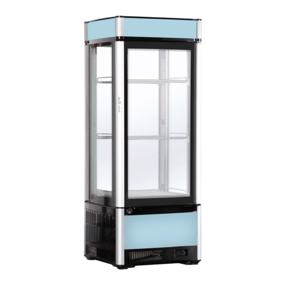
- Page 1 SC112N-AC Four Glass Sided Chiller Type: HSC112NA/Z157...
- Page 2 E-mail: skope@skope.com Website: www.skope.com Trademark Infringement The SKOPE trademark on this product is infringed if the owner, for the time being, does any of the following: • Applies the trade mark to the product after its state, condition, get-up or packaging has been altered in any manner •...
-
Page 3: Table Of Contents
Chiller ..........6 Model: SC112N-AC........6 Description: Four Glass Sided Chiller . - Page 4 Diagnostic Table ........37 SC112N-AC...
-
Page 5: Servicing Hydrocarbon
Special service requirements are needed as R600a is a flammable refrigerant. Safety hazards The main R600a safety hazards are: Flammable refrigerant. Venting of R600a and compressor oil. Asphyxiation. SKOPE does NOT recommend performing hazardous activities on the refrigeration system. Servicing Hydrocarbon Service Manual... -
Page 6: Specifications
SC112N-AC Specifications Chiller Model: SC112N-AC Description: Four Glass Sided Chiller Type: HSC112NA/Z157 Dimensions External Internal 1165-1180mm 725mm Height 470mm 382.6mm Width Depth 470mm 369.5mm 0.22m Floor area Refrigeration system Bottom-mounted, integral, electronically controlled refrigeration system Electronic controller CAREL ECOBOX Refrigerant... -
Page 7: Electronic Controller
Electronic Controller Electronic Controller Operations Introduction The SC112N-AC chiller is fitted with a CAREL ECOBOX electronic controller. The electronic controller is visible on the front panel and is housed inside the controller box at the front of the refrigeration system. -
Page 8: Faceplate
SC112N-AC Faceplate Because the electronic controller plays such an important role, it’s helpful to know the parts of the faceplate you may use. Figure 2: Electronic controller faceplate Item Description Alarm Mute (up): Mutes the audible alarm buzzer. Day - Night: Switches the chiller between ‘Day’ and ‘Night’... -
Page 9: Running The Chiller
SC112N-AC Running the Chiller Operating The electronic controller will automatically switch the chiller between ‘Day’ Modes and ‘Night’ modes depending on use, and into Cold Climate Protection (CCP) mode if necessary (see “Cold Climate Protection” on page 10). If the front door (on the electronic controller side) is not opened for four hours, the chiller will automatically enter ‘Night’... -
Page 10: Messages And Alarms
SC112N-AC Messages and Alarms Controller The following table explains messages that the electronic controller Display displays, and related alarms. Alarms signal unexpected operational changes in the chiller and can be muted by pressing the Alarm Mute (up) button on the electronic controller faceplate (see page 8). -
Page 11: Programming The Electronic Controller
SC112N-AC Programming the Electronic Controller Parameters The parameter configuration program is set by SKOPE at the factory. A label on the controller box indicates the parameter configuration program number (e.g. the SC112N-AC chiller uses program ‘089’). The electronic controller parameters can be modified using the keypad. - Page 12 SC112N-AC Parameter list – SC112N-AC program 089 Electronic Controller Parameter Sheet Revision No. 032 - B600F-3 (CO2) #N/A SC112A-AC Application Full List ECOBox EVO Controller Type SET0 PZHBC0H00VK (Rev 1.422) Controller Model & Revision ELZ10900 SKOPE Part Number CPS1014-036-SET0 Last Revised on:...
- Page 13 SC112N-AC Electronic Controller Service Manual...
-
Page 14: Wiring
SC112N-AC Wiring Model: SC112N-AC GNYE Surge Protector Condenser Motor CAREL Controller Compressor Start Main Winding Winding Capacitor Relay Comp Motor Protector ACC Compressor AUX 1 12Vdc Power Supply All Cabinet AUX 2 Lighting Cabinet Temp. Probe Evaporator Evap Temp. Motor... -
Page 15: Notes
SC112N-AC Notes Wiring Service Manual... -
Page 16: Spare Parts
SC112N-AC Spare Parts Cabinet Assembly Spare Parts Service Manual... -
Page 17: Parts - Cabinet
SC112N-AC Parts – Cabinet Item Description SKOPE Part No. Customer Part No. Glass door assembly HB0070807597 120076272 Top hinge HB0070109359 120076274 Side panel HB0070204927 120076275 Lower side panel HB0070204933 120076276 LED strip light (bottom sign) HB0071800053 Bottom sign panel (transparent) -
Page 18: Refrigeration System Assembly
SC112N-AC Refrigeration System Assembly 12 13 Spare Parts Service Manual... -
Page 19: Parts - Refrigeration System
SC112N-AC Parts – Refrigeration System Item Description SKOPE Part No. CCA-AU Part No. CCA-NZ Part No. Evaporator fan motor HB0074001220 Evaporator tub HB0070509640 120081941 Condenser fan motor HB0074001214 Condenser fan blade HB0074000311 120076300 Fan motor 12Vdc power supply HB0071800116 LED lights 12Vdc power supply... -
Page 20: Replacement Procedures
SC112N-AC Replacement Procedures Shelves Adjusting the The chiller is supplied with three wire shelves which may be positioned at different heights to suit various products. Each shelf is held in place with four Shelves shelf clips which engage in the corner shelf support strips. -
Page 21: Lights
SC112N-AC Lights The chiller is lit by four interior pillar lights, four top sign lights and two bottom sign lights. All lights are powered by a 12Vdc LED power supply located within the refrigeration system (see page 27). If one or several individual light/s fail on a light strip, the remaining lights will still receive power and should work. -
Page 22: Top Sign Lights
SC112N-AC Top Sign Lights The chiller has four lit top signs, one on each side of the chiller. Each sign is lit by one LED strip light (see page 17 for spare parts). To replace a top sign light 1. Isolate the chiller from the power supply by unplugging from the wall socket. -
Page 23: Doors
SC112N-AC Doors The chiller is fitted with a front and back door. The front door is on the electronic controller side and is fitted with a door switch to monitor door openings. The front door should be directed towards the customer. The rear door is not fitted with a door switch and should face away from the customer. -
Page 24: Adjusting Door Tension
Refrigeration System Before Overview Servicing Ensure you have read and understood this manual before starting any servicing. Important. SKOPE hydrocarbon refrigeration systems must only be serviced by appropriately skilled and qualified refrigeration mechanics. Replacement Procedures Service Manual... - Page 25 Check all components including the electronic controller and electrical systems. Ensure your work area is well ventilated. IMPORTANT Use only dedicated hydrocarbon SKOPE OEM spare parts. DO NOT use alternative parts. For safety compliance, use only SKOPE-supplied components specified for the appliance.
-
Page 26: On-Site Work
▪ Must have no ignition sources, nor any areas where the gas may pool. Must be able to transport swap units. Should carry minimum SKOPE hydrocarbon service parts. On-site Work The service technician must have required knowledge, skills, qualifications, and tools before beginning any on-site work on the refrigeration sealed system. -
Page 27: Refrigeration Unit Assembly
SC112N-AC The SC112N-AC refrigeration system is a bottom-mounted, electronically controlled serviceable system. It is made up of three levels, each containing specific parts and assemblies. Specifications for the refrigeration system are in the following table. Verify basic requirements before servicing. -
Page 28: Refrigeration System Access
SC112N-AC Refrigeration The following instructions detail accessing the refrigeration system. System Servicing can be completed by separating the top cabinet assembly from the Access bottom refrigeration system. To access the refrigeration system 1. Isolate the chiller from the power supply by unplugging from the wall socket. -
Page 29: Refrigeration System Dismantling
SC112N-AC Fixing screw Fixing screw 6. Undo the top four screws from each refrigeration system pillar support bracket (16 screws in total) to detach the top part of the chiller. 7. Lift the top cabinet assembly from the bottom refrigeration system. It may be necessary for a second person to hold the bottom refrigeration system while separating. - Page 30 SC112N-AC 5. Free all pipes and cables from the putty on the evaporator tray edge, detach the drain pipe from the bottom of the evaporator tray, and carefully pivot the evaporator tray out from under the evaporator coil. Place the tray aside.
-
Page 31: Evaporator Fan
SC112N-AC Evaporator The evaporator fan is located on the top level (level three) of the refrigeration system. It is mounted on the evaporator shroud, on top of the evaporator tray. The complete fan (motor and blade) is replaced as one part. -
Page 32: Power Supply And Surge Protector
SC112N-AC 4. Trace the condenser fan cable to its connector plug and unplug the condenser fan (cut the cable ties if necessary). 5. Detach the condenser fan motor by undoing the two nuts on the underside of the condenser fan baffle. -
Page 33: Compressor Electrics
SC112N-AC To access the compressor 1. Isolate the chiller from the power supply, separate the top cabinet assembly from the bottom refrigeration system and gain access to level one of the refrigeration system (see page 29). 2. Service as necessary. -
Page 34: Electronic Controller
SC112N-AC Electronic Controller Electronic The electronic controller is located at the front of the chiller behind the lower Controller bottom panel and is visible from the front of the chiller. For information on Assembly operation and programming, refer to the Electronic Controller section of this manual on page 7. -
Page 35: Controller Terminals
SC112N-AC Controller Refer to Figure 8 below for controller termination details. Terminals Door switch Black Evaporator probe Black Black White Control probe Blue Supply Brown Black Compressor Brown White Fans Figure 8: Controller Lights termination Control Probe The control probe is attached to a bracket on the evaporator shroud and plugs into the rear of the electronic controller. -
Page 36: Door Switch
SC112N-AC 4. Detach the evaporator shroud by undoing the four fixing screws. Place aside. 5. Withdraw the probe from the evaporator coil and trace the probe cable back to the terminals at the rear of the electronic controller. Unplug from the controller. -
Page 37: Troubleshooting
SC112N-AC Troubleshooting Diagnostic For problems with the cabinet and refrigeration unit, use the following table. Table Problem Possible Cause Suggestions • Chiller not operating. • Loss of power supply. • Check mains power supply. • Sign and/or Interior • Electronic controller •... - Page 38 SKOPE Industries Limited ABN: 73 374 418 306 AU: 1800 121 535 NZ: 0800 947 5673 skope@skope.com www.skope.com...
Need help?
Do you have a question about the SC112N-AC and is the answer not in the manual?
Questions and answers