Table of Contents
Advertisement
Quick Links
8 Channel Video Receive Unit with Bi-directional Data and
Audio Channels plus Ethernet for a Dual Redundant fibre
ring using CWDM - includes AMG NMS Network
The AMG3788BERN-DR-CWDMn/m is a rackmount eight channel video receive unit designed to
receive 8 video signals from a single optical fibre ring with Dual Redundant operation. It also provides
bi-directional data channels via a low speed data interface, plus full duplex 100BaseT Ethernet
connectivity around the ring.
The AMG3788BERN-DR-CWDMn/m is designed to plug into an AMG2005 subrack, which in turn fits
into a 19" rack system. It also includes an AMG Management Interface to allow management of the
system using the AMG SNMP enabled Management software.
The AMG3788BERN-DR-CWDMn/m is designed to operate with AMG3713BxE-DR-SF-CWDMn/m-C
or rackmount equivalent AMG3713BxER-DR-SF-CWDMn/m-C single channel video, data and
Ethernet insert units. It may also be used with other combinations of single, dual and four channel
video, data and Ethernet insert units.
An AMG3788BERN-DR-CWDMn/m receive unit will 'drop off' up to eight video channels which are
being transmitted around the fibre ring from up to eight single channel insert units, or from an
equivalent combination of multi-channel insert units.
AMG Systems Ltd. reserves the right to make changes to this
document without notice. The information herein is believed to
be accurate. No responsibility is assumed by AMG for its use.
Management Interface
AMG3788BERN-DR-
CWDMn/m
Instruction Manual
Page 1 of 20
AMG3788BERN-DR-CWDMnm
Instruction Sheet D16681-03.doc
Advertisement
Table of Contents

Related Manuals for AMG AMG3788BERN-DR-CWDMn/m


Summary of Contents for AMG AMG3788BERN-DR-CWDMn/m
- Page 1 The AMG3788BERN-DR-CWDMn/m is designed to plug into an AMG2005 subrack, which in turn fits into a 19" rack system. It also includes an AMG Management Interface to allow management of the system using the AMG SNMP enabled Management software.
-
Page 2: Table Of Contents
Network Alarm Port .......................... 15 The Management Interface ......................15 Alarm Output and Reset Operation ....................17 AMG Systems Ltd. reserves the right to make changes to this Page 2 of 20 AMG3788BERN-DR-CWDMnm document without notice. The information herein is believed to Instruction Sheet D16681-03.doc... - Page 3 Mounting Details..........................18 Removal / replacement from / to the Case..................18 Safety Maintenance and Repair AMG Systems Ltd. reserves the right to make changes to this Page 3 of 20 AMG3788BERN-DR-CWDMnm document without notice. The information herein is believed to Instruction Sheet D16681-03.doc...
-
Page 4: Introduction
Introduction Unit Functional Schematic The AMG3788BERN-DR-CWDMn/m transmits and receives optical signals from both a primary and a secondary optical channel. The optical channels operate at wavelengths defined by 'n' and 'm' in the CWDMn/m part number and are transmitted on the same optical fibre in different directions, using external optical couplers to connect 3788BERN-DR-CWDMn/m to the single fibre loop. -
Page 5: Dual Redundant Operation
8 channel video transmission system as illustrated below. If a fibre link is broken, operation of the ring continues by making use of the secondary optical fibre route as below: AMG Systems Ltd. reserves the right to make changes to this Page 5 of 20 AMG3788BERN-DR-CWDMnm document without notice. - Page 6 4,5,6,7 and 8 remains fully functional. Note that where necessary repeaters can be added at nodes to increase the average distance between nodes. AMG Systems Ltd. reserves the right to make changes to this Page 6 of 20 AMG3788BERN-DR-CWDMnm document without notice.
-
Page 7: Connections
DATA CHANNEL B Data Connector ........RJ45 Channel B Interface......Defined by data/audio interface daughter board fitted into Slot 1 on main board and indicated by the 'x' in the AMG partno. Video Output Connections No. of channels........8 Connectors .......... 75 ohm BNC Socket. -
Page 8: Ethernet Operation
Ethernet Operation In order for the AMG system to transmit Ethernet signals, an onboard RJ45 Ethernet interface or X16003 Ethernet interface adaptor should be fitted to all units in the ring. The Ethernet interface can operate at either 10Mbits/s half duplex, or 100Mbit/s full duplex. When all the Ethernet interfaces around the ring are operating at 100Mbit/s full duplex the system behaves as a multi-port repeater. -
Page 9: Data And Audio Channel Configuration
Bank B carries up to 8 channels of data / audio, the physical interface of which is determined by fitment of AMG data or audio daughter boards onto the B Channel data expansion board slots. -
Page 10: Data Interface Connections Channel A
RS485 bus high (+5 volts) and the other arm low (0 volts) using high value resistors within the third party equipment. In order to ensure that the AMG equipment detects a tri-state condition, then these resistors should have a value above 5kΩ. If the third party bias resistors are less the 750Ω... -
Page 11: Data And Audio Channel Configuration
Data and Audio Channel Configuration The data expansion board slots are accessed by removing the AMG unit from its case. A data channel is active when a daughter board is installed in the required data channel slot. Each data interface board enables one bi-directional channel. -
Page 12: Data And Audio Connections Bank B
See Data or Audio Daughter Board Instruction Sheet for meaning of Audio/Data IN+, Audio/Data IN- Audio/Data OUT+, and Audio/Data OUT- for each data type. AMG Systems Ltd. reserves the right to make changes to this Page 12 of 20 AMG3788BERN-DR-CWDMnm document without notice. -
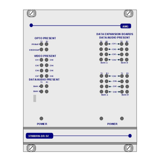
Page 13: Front Panel Indicators
(+V) present on IN+ logic transitions present on IN+ logic one (-V) present on IN+ AMG Systems Ltd. reserves the right to make changes to this Page 13 of 20 AMG3788BERN-DR-CWDMnm document without notice. The information herein is believed to Instruction Sheet D16681-03.doc... - Page 14 > 0dBm (overload at +6dBm) audio not present or < -40dBm This represents the audio signals being received from the optical fibre. AMG Systems Ltd. reserves the right to make changes to this Page 14 of 20 AMG3788BERN-DR-CWDMnm document without notice.
-
Page 15: Network Management
Power at the receiver Closed by: Reset The Management Interface The Management Interface is fitted to AMG receivers / transmitters and is signified by a 'N' in the part number AMG Systems Ltd. reserves the right to make changes to this... - Page 16 Each management interface, thus each receiver or transmitter, has an ID number with is identified below the management port. This ID number is used by the AMG Network Management System (NMS) to identify the unit. The physical interface is a 9 way female D-type connector. It supports either RS-232 or RS-485.
-
Page 17: Alarm Output And Reset Operation
On release of the alarm reset, the alarm output will remain in a closed state until the next change of state to the AMG transmit unit connected to the receiver. The alarm output may not register a change of state which happens within 5 seconds of release of the alarm reset. - Page 18 There are no user serviceable parts within AMG products. See unit data sheet for full specification. In case of problem or failure, please call your local support centre or contact: AMG Systems Ltd. at 3 The Omega Centre, Stratton Business Park, Biggleswade, Beds., SG18 8QB, UK.
- Page 19 This page is intentionally blank. AMG Systems Ltd. reserves the right to make changes to this Page 19 of 20 AMG3788BERN-DR-CWDMnm document without notice. The information herein is believed to Instruction Sheet D16681-03.doc be accurate. No responsibility is assumed by AMG for its use.
- Page 20 This page is intentionally blank. AMG Systems Ltd. reserves the right to make changes to this Page 20 of 20 AMG3788BERN-DR-CWDMnm document without notice. The information herein is believed to Instruction Sheet D16681-03.doc be accurate. No responsibility is assumed by AMG for its use.
Need help?
Do you have a question about the AMG3788BERN-DR-CWDMn/m and is the answer not in the manual?
Questions and answers