Table of Contents
Advertisement
Quick Links
8 Channel Video Receive Unit with up to 9 Bi-directional
Data / Audio Channels plus Ethernet for a Dual Redundant
fibre ring - includes AMG NMS Network Management
The AMG3788BERN-DR is a rackmount eight channel video receive unit designed to receive up to 8
video signals from a dual fibre optical fibre ring with Dual Redundant operation. It also provides 9
bi-directional data/audio channels via a low speed data interface, plus full duplex 100BaseT Ethernet
connectivity around the ring. Eight of the data/audio channel interfaces, whether RS-232, RS-422,
RS-485, 20mA, TTL, Contact Closure, Lonworks or Audio, are defined at manufacture by the addition
of daughter boards fitted onto the Data Expansion Board B.
The AMG3788BERN-DR is designed to plug into an AMG2005 subrack, which in turn fits into a 19"
rack system. It also includes an AMG Management Interface to allow Management of the system using
the AMG SNMP enabled Management software.
The AMG3788BERN-DR is designed to operate with up to eight AMG3717BE-DR single channel
video insert units. Each receiver will 'drop off' up to eight video channels which are being transmitted
around the fibre ring. The AMG3788BERN-DR may also be used with other combinations of single,
dual or four channel video and data insert units.
AMG Systems Ltd. reserves the right to make changes to this
document without notice. The information herein is believed to
be accurate. No responsibility is assumed by AMG for its use.
AMG3788BERN-DR
Instruction Manual
Interface
Page 1 of 18
AMG3788BERN-DR Instruction Sheet
D16870.doc
issue 01
Advertisement
Table of Contents

Related Manuals for AMG AMG3788BERN-DR


Summary of Contents for AMG AMG3788BERN-DR
- Page 1 Data Expansion Board B. The AMG3788BERN-DR is designed to plug into an AMG2005 subrack, which in turn fits into a 19" rack system. It also includes an AMG Management Interface to allow Management of the system using the AMG SNMP enabled Management software.
-
Page 2: Table Of Contents
The Management Interface....................... 14 Alarm Output and Reset Operation ....................16 Physical Information Dimensions ............................17 AMG Systems Ltd. reserves the right to make changes to this Page 2 of 18 AMG3788BERN-DR Instruction Sheet document without notice. The information herein is believed to D16870.doc... - Page 3 Removal / replacement from / to the Case..................17 Safety Maintenance and Repair AMG Systems Ltd. reserves the right to make changes to this Page 3 of 18 AMG3788BERN-DR Instruction Sheet document without notice. The information herein is believed to D16870.doc...
-
Page 4: Introduction
This signal will be repeated around the ring to get back to this AMG3788BERN-DR on the secondary route. As the primary input is not present on this unit, the data signal will now be taken from the secondary optical input. Thus maintaining integrity of the data transmission. - Page 5 The AMG3788BEN-DR or rackmount AMG3788BERN-DR is designed to be connected in a ring or point to point system. In a ring system, single, dual and four channel insert units respectively can be combined to make up an 8 channel video transmission system as illustrated below.
-
Page 6: Connections
On Board Data Interface – RS232, RS422 or RS485. Selected by slide switch below RJ45 connector. RS232 – switch position - high (closest to BNC connections) AMG Systems Ltd. reserves the right to make changes to this Page 6 of 18 AMG3788BERN-DR Instruction Sheet document without notice. -
Page 7: Ethernet Operation
Ethernet Operation In order for the AMG system to transmit Ethernet signals, an onboard RJ45 Ethernet interface or X16003 Ethernet interface adaptor should be fitted to all units in the ring. The Ethernet interface can operate at either 10Mbits/s half duplex, or 100Mbit/s full duplex. When all the Ethernet interfaces around the ring are operating at 100Mbit/s full duplex the system behaves as a multi-port repeater. -
Page 8: Data And Audio Channel Configuration
Bank B carries up to 8 channels of data / audio, the physical interface of which is determined by fitment of AMG data or audio daughter boards onto the B Channel data expansion board slots. -
Page 9: Data Interface Connections Channel A
Data and Audio Channel Configuration The data expansion board slots are accessed by removing the AMG unit from its case. A data channel is active when a daughter board is installed in the required data channel slot. Each data interface board enables one bi-directional channel. -
Page 10: Daughter Board Layout
Note that the data and audio channel numbers are associated with each slot. This allocates the pin numbers on the rear panel connector together with the front panel LED indicators. AMG Systems Ltd. reserves the right to make changes to this Page 10 of 18 AMG3788BERN-DR Instruction Sheet document without notice. -
Page 11: Data And Audio Connections Bank B
See Data or Audio Daughter Board Instruction Sheet for meaning of Audio/Data IN+, Audio/Data IN- Audio/Data OUT+, and Audio/Data OUT- for each data type. AMG Systems Ltd. reserves the right to make changes to this Page 11 of 18 AMG3788BERN-DR Instruction Sheet document without notice. -
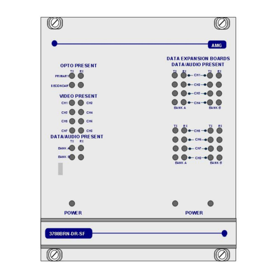
Page 12: Front Panel Indicators
(+V) present on IN+ logic transitions present on IN+ logic one (-V) present on IN+ AMG Systems Ltd. reserves the right to make changes to this Page 12 of 18 AMG3788BERN-DR Instruction Sheet document without notice. The information herein is believed to D16870.doc... - Page 13 > 0dBm (overload at +6dBm) audio not present or < -40dBm This represents the audio signals being received from the optical fibre. AMG Systems Ltd. reserves the right to make changes to this Page 13 of 18 AMG3788BERN-DR Instruction Sheet document without notice.
-
Page 14: Network Management
Power at the receiver Closed by: Reset The Management Interface The Management Interface is fitted to AMG receivers and is signified by a 'N' in the part number AMG Systems Ltd. reserves the right to make changes to this Page 14 of 18 AMG3788BERN-DR Instruction Sheet document without notice. - Page 15 Each management interface, thus each receiver, has an ID number with is identified below the management port. This ID number is used by the AMG Network Management System (NMS) to identify the unit. The physical interface is a 9 way female D-type connector. It supports either RS-232 or RS-485.
-
Page 16: Alarm Output And Reset Operation
On release of the alarm reset, the alarm output will remain in a closed state until the next change of state to the AMG transmit unit connected to the receiver. The alarm output may not register a change of state which happens within 5 seconds of release of the alarm reset. -
Page 17: Physical Information
The unit is designed to be mounted within a 2005 / 2009 Subrack on standard card guides. Note the AMG standard racks are supplied with guide rails every 7HP. In order to fit this unit in the subrack, 2 sets of card guides have to be removed by pulling gently on the card guides. - Page 18 This page is intentionally blank. AMG Systems Ltd. reserves the right to make changes to this Page 18 of 18 AMG3788BERN-DR Instruction Sheet document without notice. The information herein is believed to D16870.doc be accurate. No responsibility is assumed by AMG for its use.
Need help?
Do you have a question about the AMG3788BERN-DR and is the answer not in the manual?
Questions and answers