Table of Contents
Advertisement
Quick Links
Advertisement
Table of Contents

Related Manuals for 96Boards WinLink E850

Summary of Contents for 96Boards WinLink E850
- Page 1 WinLink E850-96 CE Board Hardware User Manual Version 1.12, Dec 2022...
-
Page 2: Table Of Contents
E850-96Board Development Board Hardware User Guide Table of Contents Table of Contents ..................................2 Introduction ....................................3 What’s in the Box ..................................4 Board Overview .................................... 5 Key Components ................................... 6 System Block Diagram .................................. 7 Getting Started ..................................... 7 Prerequisites .................................. -
Page 3: Introduction
E850-96Board Development Board Hardware User Guide Introduction The WinLink E850 Development Board is a 96Boards compliant community board based on Samsung Exynos 850 platform. The following table lists its key features: Processor Samsung Exynos 850, S5E3830 Octa-core ARM@Cortex-A55 operating at up to 2.0GHz •... -
Page 4: What's In The Box
E850-96Board Development Board Hardware User Guide What’s in the Box The box contains one WinLink E850 Development Board. Power Adaptor for E850 board also provided. Documents and downloads available at; https://www.96boards.org/documentation/consumer/e850-96b/ 4/21 WinLink... -
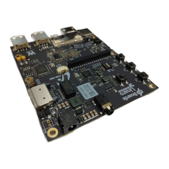
Page 5: Board Overview
E850-96Board Development Board Hardware User Guide E850-96 Development Board Board Overview ○ ○ ⑩ ○ ⑮ ○ ○ ⑤ ○ ① +② ③ ⑦ ④ ○ ○ ⑫ ○ ⑥ ⑧ ⑬ ⑭ ⑪ 5/21 WinLink... -
Page 6: Key Components
E850-96Board Development Board Hardware User Guide Key Components Position Reference Description Samsung Exynos 850 SoC(Bottom Side) 8GB/64GB eMCP(Bottom side) WIFI/Bluetooth S612 PMIC (S2MPU12) Low Speed Expansion Connector High Speed Connector Bluetooth/WLAN Antenna Micro SD Card Socket HDMI Type A Port RJ-45 Micro USB Type B Connector LED7... -
Page 7: System Block Diagram
Development Board Hardware User Guide System Block Diagram Getting Started Prerequisites Before you power up your WinLink E850 Development Board for the first time you will need the following: WinLink E850 Development Board A 96Boards compliant power supply (included in box ). -
Page 8: Component Details
Integrated power detector to support per packet Tx power control The WinLink E850 Development Board also has a RF connector to connect the external antenna or other RF device. If you want to use this function, you should put the cable to CN7 connector(MS-156C2:Hirose). It will automatically switch RF input from chip antenna(ANT1) to connected device(CN7). -
Page 9: Bluetooth
HDMI The 96Boards specification calls for an HDMI port to be present on the board. The Exynos 850 doesn’t include a built-in HDMI interface. The WinLink E850 Development Board deploys the built-in DPI interface as the source for the HDMI output. -
Page 10: Usb Host Ports
Port 3 of the USB HUB is routed to the High Speed Expansion connector. USB Device ports The WinLink E850 Development Board implements a device port. The port is located at J1, a Micro USB type B. It is routed to USB_P0 interface of Exynos 850. -
Page 11: Buttons
Development Board Hardware User Guide Buttons The WinLink E850 Development Board presents four buttons. They are Power key, VOL up key, VOL down key and Reset key. The power ON/OFF and RESET signals are also routed to the Low Speed Expansion connector. -
Page 12: Led Indicators
Three LEDs: The three user LEDs are surface mount Green in 0603 size located next to the micro USB connector. The WinLink E850 Development Board drives the three LEDs from the Exynos 850 XGPIOs; X1 : XGPIO10/GPG2[2] – Heart beat LED X2 : XGPIO11/GPG2[3] –... - Page 13 E850-96Board Development Board Hardware User Guide CN5 : 12507WR-03L(YEONHO, 3-pin 1.25mm) Mating connector : 12505HS-03(YEONHO), 51021-0300(Molex) 13/21 WinLink...
-
Page 14: Expansion Connectors
E850-96Board Development Board Hardware User Guide Expansion Connectors Low Speed Expansion Connector The following tables show the Low Speed Expansion Connector pin out: 96Boards Signals WinLink E850 Development Board Signals Note(Exynos 850 pin) UART0_CTS LS_UART0_CTS XUSI_CMGP0_CTSN_CSN UART0_TxD LS_UART0_TxD XUSI_CMGP0_TXD_DO_SDA0 UART0_RxD... - Page 15 The 96Boards specification calls for one SPI bus master to be provided on the Low Speed Expansion Connector. The WinLink E850 Development Board implements a full SPI master with 4 wires, CLK, CS, MOSI and MISO. The signals are connected directly to the Exynos 850 SoC and driven at 1.8V.
-
Page 16: High Speed Expansion Connector
E850-96Board Development Board Hardware User Guide Power Supplies The WinLink E850-96Boards specification calls for three power rails to be present on the Low Speed Expansion Connector: +1.8V Max of 100mA +5V Provide a minimum of 7.5W of power (2.5A). SYS_DCIN 12-18V input with enough current to support all the board functions. - Page 17 Pull-up to VIO18_PMU via 100K resistor MIPI DSI 0 The 96Boards specification calls for a MIPI-DSI to be present on the High Speed Expansion Connector. A minimum of one lane is required and up to four lanes can be accommodated on the connector.
-
Page 18: Audio Connector
SD/SPI The 96Boards specification calls for an SD interface or a SPI port to be part of the High Speed Expansion Connector. The WinLink E850 Development Board implements a full SPI master with 4 wires (96Boards SPI Configuration), CLK, CS, MOSI and MISO. -
Page 19: Power Management Overview
E850-96Board Development Board Hardware User Guide Power Management Overview Block Diagram DC Power Input An 12V to 18V power from a dedicated DC jack CN2. An 12V to 18V power from the SYS_DCIN pins on the Low Speed Expansion Connector J5. ... -
Page 20: Voltage Rails
E850-96Board Development Board Hardware User Guide Voltage Rails Default ON Iout Max Circuit Type Net Name Connected Net(s) (mA) Voltage(V) Sys.BUCK V_SYS 8000 System Power : 5V (MP2386 output) BUCK1_PMIC 0.75 1500 VDD_CPU of Exynos 850 BUCK2_PMIC 0.75 4000 VDD_INT of Exynos 850 BUCK3_PMIC 0.75 3000... -
Page 21: Mechanical Specification
E850-96Board Development Board Hardware User Guide Mechanical specification 2D Reference Drawing * WinLink E850 Development Board meets 96Boards™ Consumer Edition extended dimensions specifications. 21/21 WinLink...