Table of Contents
Advertisement
Quick Links
ROCK960 Development Board User Manual
Table of Contents
Table of Contents
Introduction
Key Components
GPS
HDMI
USB Device ports
Audio
Analog Expansion Connector
Power Source Selection and Sequencing
Introduction
The ROCK960 Development Board is a 96Boards compliant community board based
on Rockchip RK3399 platform.The following table lists its key features:
Advertisement
Table of Contents

Related Manuals for 96Boards ROCK960

Summary of Contents for 96Boards ROCK960
-
Page 1: Table Of Contents
Analog Expansion Connector Power Management Overview Block Diagram DC Power Input Power Source Selection and Sequencing Voltage Rails Mechanical Specification Introduction The ROCK960 Development Board is a 96Boards compliant community board based on Rockchip RK3399 platform.The following table lists its key features:... - Page 3 Component Description Rockchip RK3399 ARM Cortex-A72 Dual-core up to 1.8GHz + Cortex A53 Quad-core up to 1.4GHz ARM Mali T860MP4 2GB or 4GB LPDDR3 @ 1866MHz RK805 Storage 16/32GB eMMC 5.1 Ethernet USB 2.0/3.0 expansion Port WLAN 802.11 ac/a/b/g/n, 2xMIMO, 2.4GHz and 5Ghz, Wireless Bluetooth 4.2.
-
Page 4: What's In The Box
Recommend a 12V@2A adapter with a DC plug which Power has a 4.75mm outer diameter and 1.7mm center pin Source with standard center-positive (EIAJ-3 Compliant) AOSP/Debian/Ubuntu/Fedora/LibreELEC/Lakka/FlintOS Support Size 85mm x 55mm Back to top What’s in the Box The standard ROCK960 packages contains the follow:... -
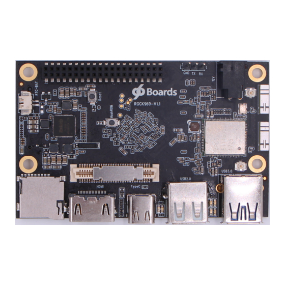
Page 5: Board Overview
Main board 12V/2A power adapter Transparent acrylic case Screws(M3) Heatsink(22mm x 22mm) Heatsink Plaster Back to top Board Overview... -
Page 6: System Block Diagram
Back to top System Block Diagram... -
Page 7: Getting Started
Back to top Getting Started Prerequisites Before you power up your ROCK960 Board for the first time you will need the following: ROCK960 Board, model A or model B. A 96Boards compliant power supply (sold separately). A HDMI or DVI LCD Monitor that supports a resolution of 720p/1080P/4K. -
Page 8: Starting The Board For The First Time
Starting the board for the first time To start the board, follow these simple steps: 1. Connect the HDMI cable to the ROCK960 Board HDMI connector and to the LCD Monitor. 2. Connect the keyboard to USB connector marked USB2.0 and the mouse to the USB connector marked USB3.0. -
Page 9: Memory (Dram)
It meets the SD3.0 standard. Boot ROM The ROCK960 Board can boot up from the EMMC or the Micro SD card. If a bootable Micro SD card is inserted, ROCK960 will boot from Micro SD card and ignore the EMMC. If the Micro SD card is not inserted or non-bootable(ie. as storage media). -
Page 10: Bluetooth
Supports 20, 40, 80 MHz channels with optional SGI(256 QAM modulation) Supports IEEE 802.11 ac/n beam forming The ROCK960 Board also has a RF connector to connect the external antenna or other RF device. If you want to use this function, you should change the 0ohm resistor directions besides the antenna. -
Page 11: Usb Host Ports
Note: the type C port can work in one mode at a time, Host mode or Device mode, not both. Audio The ROCK960 Board has four audio ports: BT, HDMI, I2S and DP. DC Power The ROCK960 Board can be powered by two ways:... -
Page 12: Uart
Two activity LEDs WiFi activity LED –The ROCK960 Board drives this Yellow LED via GPIO4_D5(GPIO number 1157), an IO from RK3399. BT activity LED –The ROCK960 Board drives this Blue LED via GPIO4_D6(GPIO number 1158), an IO from RK3399. Four User LEDs The four user LEDs are surface mount Green in 0603 size located between two USB type A ports. -
Page 13: Additional Functionality
LED3 : GPIO4_D0, GPIO number 1152 LED4 : GPIO4_D4, GPIO number 1156 Additional Functionality The ROCK960 has an additional M.2 connector, which expose the 4 lanes PCIE 2.1 signal from RK3399, a M.2 SSD can be connected to add more storage. Back to top... - Page 14 The 96Boards specifications calls for a 4-wire UART implementation, UART0 and an optimal second 2-wire UART, UART1 on the Low Speed Expansion Connector. The ROCK960 Board implements UART0 as a 4-wire UART that connects directly to the RK3399 SoC. These signals are driven at 1.8V.
- Page 15 The 96Boards specification calls for one SPI bus master to be provided on the Low Speed Expansion Connector. The ROCK960 Board implements a full SPI master with 4 wires, CLK, CS, MOSI and MISO. The signals are connected directly to the RK3399 SoC and driven at 1.8V.
-
Page 16: High Speed Expansion Connector
USB host connectors and the HDMI 5V power to the HDMI connector. The remaining capacity provides a max current of 2A to the Low Speed Expansion Connector, for a total of 10W which meets the 96Boards requirements. SYS_DCIN Can serves as the board’s main power source or can receive power from the board. - Page 17 100K resistor MIPI DSI 0 The 96Boards specification calls for a MIPI-DSI to be present on the High Speed Expansion Connector. A minimum of one lane is required and up to four lanes can be accommodated on the connector.
- Page 18 MIPI-CSI1, the companion I2C is I2C3. Each of the I2C line’s pull up can be set from RK3399 internally. SD/SPI The 96Boards specification calls for an SD interface or a SPI port to be part of the High Speed Expansion Connector. The ROCK960 Board implements a full SPI master with 4 wires (96Boards SPI Configuration), CLK, CS, MOSI and MISO.
-
Page 19: Power Management Overview
Others M.2/NGFF Connector ROCK960 board also exports a M.2 PCIE M key socket, which connects directly to the SoC. The M.2. socket supports M.2 M key or B&M key PCIE SSD. Back to top Power Management Overview Block Diagram DC Power Input An 8V to 18V power from a dedicated DC jack. -
Page 20: Voltage Rails
Power Source Selection The user of the ROCK960 Board should never apply power to the board from DC jack and the Low Speed Expansion connector at the same time. There is no active or passive mechanism on the ROCK960 Board to prioritize one source over the other. - Page 21 Default Iout Circuit Net Name Expected use Type Voltage(V) (mA) LDO1 LDO2 VCCA1V8_HDMI HDMI/MIPI TX pay PMUIO/PMU PLL/USB LDO3 VCCA_1V8 phy/PCIE phy LDO4 VCC_SDIO SDMMC0 LDO5 LDO6 VCC_1V5 APIO2/APIO4 LDO7 VCCA0V9_HDMI HDMI/MIPI TX phy LDO8 VCC_3V0 APIO2/APIO4/PMUIO2 0.7125- BUCK VDD_CPU_B 1000 Dual A72 cores 0.7125-...
-
Page 22: Mechanical Specification
Default Iout Circuit Net Name Expected use Type Voltage(V) (mA) Other 8-18V DCIN on LS DC_IN 8 ~ 18 1000 connector as output 8-18V DCIN on LS DC_IN 8 ~ 18 3000 connector as input Back to top Mechanical Specification 2D Reference Drawing Back to top...