
Related Manuals for BPC instruments AMPTS III

Summary of Contents for BPC instruments AMPTS III
- Page 1 OPERATION AND MAINTENANCE MANUAL AMPTS III Anaerobic batch fermentation test systems Contact Us : www.bpcinstruments.com +46 (0)46 163950 Mobilvägen 10, 223 62 Lund, Sweden...
- Page 2 This document contains proprietary information protected by copyright. No part of this publication may be redistributed in any form whatsoever or translated into any language without prior, written permission of BPC Instruments AB. © 2023 BPC Instruments AB. All rights reserved.
-
Page 3: Table Of Contents
Chapter 02: Delivery Checks………………………………………………………………………………………. Chapter 03: Equipment Description…………………………………………………………………………… Chapter 04: Setting up the Instrument………………………………………………………………………. Chapter 05: AMPTS III and AMPTS III Light DUO…………………………………………………………. 20 Chapter 06: AMPTS III Web-based Software………………………………………………………………. 22 6.1 Computer Network Configuration……………………………………………… 6.2 Network Quick Guide…………………………………………………………………. 22 6.3 Web-based Software Aurora... -
Page 4: General Information
Make sure to tie back any hanging objects, such as hair and clothing, when working near rotating or other moving parts. Do not modify the instrument without the prior consent of the manufacturer. BPC Instruments AB do not assume responsibility for any errors due to equipment modification. - Page 5 The product warranty provided with the instrument corresponds to the stipulations in Orgalime S 2012, unless otherwise agreed upon with BPC Instruments AB. BPC Instruments AB reserves the right to correct any possible errors, mistakes, changes, updates, technical data or otherwise relevant information in this manual or any other documents, where applicable by law.
-
Page 6: Chapter 01: Overview
Chapter 01: Overview The Automatic Methane Potential Test System III (AMPTS III) is the next generation of the well-established analytical platform for conducting anaerobic batch fermentation tests developed by BPC Instruments. This new system comes with the best features of the previous generation and a series of improvements and further developments in all the different parts of the equipment. - Page 7 System log for operational diagnosis. Table 1 summarizes the new features of AMPTS III and AMPTS III Light: Table 1. Overview of the new features of AMPTS III and AMPTS III Light. AMPTS III and AMPTS III Light INCUBATION UNIT 18 channels (AMPTS III) and 9 channels (AMPTS III Light) AMPTS III standard configuration with 1 L reactors (0.5 L...
-
Page 8: Chapter 02: Delivery Checks
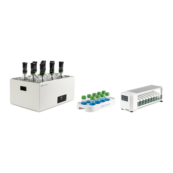
New tool for removing lids and tubing Chapter 02: Delivery Checks AMPTS III (Figure 1) and AMPTS III Light (Figure 2) are delivered with the components listed below: Figure 1. AMPTS III Complete System. Unit A – Incubation Unit 20 glass reactors (0.5 or 1 L) - Page 9 Figure 2. AMPTS III Light Complete System. Unit A – Incubation Unit 10 glass reactors (2 L) 1 motor controller signal cable 1 MCU power adapter 9 brushless DC motors 9 axis couplings for brushless 1 thermostatic water bath 1 motor power splitter...
-
Page 10: Chapter 03: Equipment Description
The MCU needs to be turned off and unplugged from the power source when any cables are connected or disconnected from the motors. Figure 4. Main features of the agitation system in AMPTS III and AMPTS III Light. - Page 11 3 mol/L NaOH solution (Figure 5). The absorption efficiency is higher than 98% even at high flow rates. Figure 5. Bottler holder designed for 9 glass bottles (250 mL). AMPTS III is equipped with two bottle holders.
- Page 12 The detection unit is equipped with an USB port for software upgrades and possible new applications and a power button. Figure 8. (A) Gas volume measuring device for AMPTS III and (B) AMPTS III Light.
- Page 13 The FCU has 2 possible resolutions, 9 mL and 2 mL for low and ultra-low gas measurements. The operational principle is based on liquid displacement and buoyance. When a certain gas volume enters the flow cell unit, the force of buoyancy leads the flow cell to open and releases the entrapped gas (Figure 9).
-
Page 14: Chapter 04: Setting Up The Instrument
Chapter 04: Setting up the Instrument In order to install the system properly, the steps described below need to be followed: Step 1: Unpack the instrument and place the thermostatic water bath on a flat and stable surface. Step 2: Remove the blue plastic protection on the thermostatic water bath lid, mount the legs and handles and place the lid on top of the thermostatic water bath. - Page 15 NOTE: Check periodically the water level inside the thermostic water bath. Step 5: Fixing the agitation system for AMPTS III. Connect the short motor cables (250 mm) in series by attaching one short motor cable to each motor (excluding the last motor in the chain), and then connecting the free end of the cable from motor 1 to the free port on motor 2 and so on until motor 9.
- Page 16 The same procedure described above can be used for AMPTS III Light. NOTE: Make sure that the power adapter for the motor controller is disconnected from the power supply when inserting or removing the motor cables. From the motor it is only possible to control the direction of the mixing, clockwise (CW), AUTO and counterclockwise (CCW).
- Page 17 Step 7: Add distilled water inside the FCU and place them on the detection unit. Make sure that each FCU is perfectly seated (horizontally levelled) on the BPC Core AMPTS Unit. It can be easily observed by checking the FCU level indicator and the level control from the software or the OLED screen as shown below.
- Page 18 Backside of the BPC Core AMPTS Unit: Step 8: Cut 36 (AMPTS III) or 18 (AMPTS III Light) pieces of festo tubing sufficient in length to connect the gas outlet of each reactor to the corresponding alkaline solution bottle (Unit B) and then a second piece to couple the glass bottle with NaOH solution to the FCU.
- Page 19 Step 9: Use the softer binder to group tubing of channels that are related to each other. If the test is conducted in triplicate, it is possible to put together six groups with three channels (tubing) each based on the content of the reactors. In order to easily identify each channel, add the multi-coloured marker clamps (two per channel) provided in different colors.
-
Page 20: Chapter 05: Ampts Iii And Ampts Iii Light Duo
Chapter 05: AMPTS III and AMPTS III Light DUO The AMPTS III and AMPTS III Light DUO was designed to increase the testing capacity for double gas measurements. This configuration consists of two BPC Core AMPTS Units, where users can measure the total gas (e.g., CH... - Page 21 Figure 11. Illustration of how AMPTS III DUO works in three stages. For AMPTS III Light DUO, the same process can be done with nine samples in 2 L reactors simultaneously. The default package comes with one BPC Core AMPTS Unit with 18 active channels for both total and single gas measurements (Figure 12).
-
Page 22: Chapter 06: Ampts Iii Web-Based Software
Leave empty Leave empty NOTE: IP address for the computer and the IP address for the AMPTS III are different. This is a design requirement of the IP protocol. Care needs to be taken so that the same address is not used in both locations, as it will render the system inaccessible from the designated computer. -
Page 23: Web-Based Software Aurora Tm
(Figure 13). In the Log in page, the default password bpc needs to be added. Figure 13. Log in page for AMPTS III and AMPTS III Light. In the Home page, users get an overview of the features of the software, where the topics are ordered according to experimental setup, execution, monitoring and finally documented. - Page 24 Additionally, several new features were implemented to offer a better user experience. In the Experiment page for AMPTS III (the same description is valid for AMPTS III Light – 9 lines), 18 lines are related to the 18 reactors where each one of them should be properly labelled based on its content.
- Page 25 The control tab is where direct interaction with the channels and motors are conducted (Figure 16). Using the Aurora software, it is possible to start and stop all or just selected channels. Figure 16. Full description of each line of the Control page. Located at the bottom right of the lines section is the control panel for the flow cell units.
- Page 26 Figure 17. Controlling the agitation system through the software. The software provides two graphs, accumulated gas volume as a function of time and flow rate as function of time. The gas volume can be presented in three different ways: without normalization, with normalization without considering the moisture content (dry), and with normalization considering the moisture content (wet).
-
Page 27: Chapter 07: Maintenance And Spare Parts
Figure 19. Report settings available in the report page. The Settings page is home to a host of settings for the instrument. It also contains valuable information regarding versions, licenses, a logfile and so forth. Sometimes, a blue triangle with a white exclamation mark will appear next to the settings tab in the Aurora software. - Page 28 All consumables are easily replaceable in the instrument. The spare parts can be ordered from BPC Instruments. For further information, please visit our webshop (link below): https://webshop.bpcinstruments.com BPC Instruments also provides a Maintenance Package where users can get all consumables that are recommended to be changed at regular intervals.
Need help?
Do you have a question about the AMPTS III and is the answer not in the manual?
Questions and answers