
Related Manuals for BPC instruments BPC Blue

Summary of Contents for BPC instruments BPC Blue
- Page 1 OPERATION AND MAINTENANCE MANUAL BPC Blue Analytical Platform for Biodegradability Analysis Contact Us : www.bpcinstruments.com +46 (0)46 163950 Mobilvägen 10, 223 62 Lund, Sweden...
- Page 2 This document contains proprietary information protected by copyright. No part of this publication may be redistributed in any form whatsoever or translated into any language without prior, written permission of BPC Instruments AB. © 2023 BPC Instruments AB. All rights reserved.
-
Page 3: Table Of Contents
LIST OF CONTENTS General Information………………………………………………………………………………………………. Chapter 01: Overview…..………………………………………………………………………………………… 6 Chapter 02: BPC Blue Configurations and Components…………..……………………………… 2.1 Anaerobic Biodegradability Analysis…………………………………………………… 2.1.1 BPC Blue Anaerobic (Default System)…………………………………………. 9 2.1.2 BPC Blue Anaerobic Light……………………………………………………………. 10 2.1.3 BPC Blue Anaerobic DUO……………………………………………………………. 12 2.1.4 BPC Blue Anaerobic Light DUO……………………………………………………... -
Page 4: General Information
Make sure to tie back any hanging objects, such as hair and clothing, when working near rotating or other moving parts. Do not modify the instrument without the prior consent of the manufacturer. BPC Instruments AB do not assume responsibility for any errors due to equipment modification. - Page 5 The product warranty provided with the instrument corresponds to the stipulations in Orgalime S 2012, unless otherwise agreed upon with BPC Instruments AB. BPC Instruments AB reserves the right to correct any possible errors, mistakes, changes, updates, technical data or otherwise relevant information in this manual or any other documents, where applicable by law.
-
Page 6: Chapter 01: Overview
BPC Blue system has been specifically designed to implement and control a wide range of standard laboratory conditions in accordance with several international protocols, providing a thorough and reproducible evaluation of the biodegradation properties of polymers. - Page 7 The following are the main new features of BPC Blue: ¨ Default setup with 18 channels. ¨ New software dedicated to biodegradability analysis. ¨ New configurations for anaerobic and aerobic tests (Light, DUO and Premium). ¨ New electronic hardware with significantly improved performance and additional functionalities.
-
Page 8: Chapter 02: Bpc Blue Configurations And Components
Chapter 02: BPC Blue Configurations and Components 2.1 Anaerobic Biodegradability Analysis Under anaerobic conditions (absence of oxygen), biodegradable materials are converted into methane (CH ), carbon dioxide (CO ), water (H O) and biomass: + CO O + C polymer... -
Page 9: Bpc Blue Anaerobic (Default System)
BPC Blue Anaerobic is suitable to perform tests in accordance with various standard protocols (Table 1): Table 1. Examples of standard protocols that can be performed using BPC Blue Anaerobic System. Protocols Description... -
Page 10: Bpc Blue Anaerobic Light
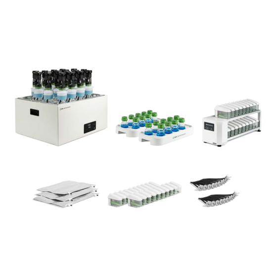
36 multi-coloured marker clamps 2.1.2 BPC Blue Anaerobic Light The light version of BPC Blue Anaerobic has the same features and functionalities as the default system, but with a reduced number of channels and different size of reactors. BPC Blue Anaerobic Light (Figure 2) comes with 9 channels and 2 L reactors. - Page 11 6 soft binders 7/180 mm FCU volume sheet 9 tubing stoppers 18 multi-coloured marker clamps Both systems operate on a mechanism that is based on biogas measurements (Figure 3): Figure 3. BPC Blue Anaerobic measures biogas produced by the biodegradation of plastic materials.
-
Page 12: Bpc Blue Anaerobic Duo
This configuration consists of two BPC Core Units, where users can measure the total gas (e.g., + CO ) and a gas component (e.g., CH ) from 18 samples simultaneously (Figure 5). Figure 5. BPC Blue Anaerobic DUO operation divided in three stages. -
Page 13: Bpc Blue Anaerobic Light Duo
36 multi-coloured marker clamps 2.1.4 BPC Blue Anaerobic Light DUO For BPC Blue Anaerobic Light DUO, the same process described above can be done with nine samples using 2 L reactors. The package comes with one BPC Core Unit with 18 active channels... - Page 14 Figure 6. BPC Blue Anaerobic Light DUO complete system. Unit A – Incubation Unit 9 glass reactors (2 L) 1 motor controller signal cable 1 MCU power adapter 9 brushless DC motors 9 axis couplings for brushless 1 thermostatic water bath...
-
Page 15: Aerobic Biodegradability Analysis
In this way, big reactors are required for the test, which affect the size and properties of the incubation unit which is used for temperature control. Alternatively, BPC Blue Aerobic System provides a simple, efficient, precise and accurate method for determining the biodegradation rate of polymers under aerobic conditions. This... - Page 16 Figure 7. Operating mechanism of BPC Blue Aerobic System. In the presence of oxygen, the biodegradation of the tested material initiates and carbon dioxide is continuously produced. The CO generated is absorbed by a 3 mol/L sodium hydroxide solution placed in the GAA unit attached to the reactor. Carbon dioxide reacts with...
- Page 17 Table 2. Examples of standard protocols that can be followed using BPC Blue Aerobic System. Protocols...
-
Page 18: Bpc Blue Aerobic (Default System)
2.2.1 BPC Blue Aerobic (Default System) BPC Blue Aerobic (Figure 8), the default package, is provided with the following components described below: Figure 8. BPC Blue Aerobic Complete System. Unit A – Incubation Unit 18 glass reactors (1 L) 1 motor controller signal cable... -
Page 19: Bpc Blue Aerobic Light
2.2.2 BPC Blue Aerobic Light Compared to the default package, BPC Blue Aerobic Light (Figure 9) is equipped with bigger reactors (2 L) and reduced number of channels (9 channels). The complete setup is listed below: Figure 9. BPC Blue Aerobic Light Complete System. -
Page 20: Bpc Blue Premium
2.3.1 BPC Blue Premium (Default System) The default package corresponds to BPC Blue Aerobic System with additional 18 stirrers to convert the setup from aerobic (Figure 10 – A) to anaerobic configuration (Figure 10 – B). In addition, this system comes 36 flow cell units, 9 mL FCUs (18 units) and 2 mL FCUs (18 units). -
Page 21: Bpc Blue Premium Light
Manifold 3 Mk 2 Mk 2 2.3.2 BPC Blue Premium Light In line with the structure described in the manual for the light versions, the BPC Premium Light variant is outfitted with 9 reactors, each with a capacity of 2 L. The components included... - Page 22 Figure 12. BPC Blue Premium Light Complete System. Unit A – Incubation Unit 9 glass reactors (2 L) 1 motor controller signal cable 1 MCU power adapter 1 motor controller unit (MCU) 9 brushless DC motors 9 axis couplings for brushless...
-
Page 23: Bpc Blue Premium Duo
Mk 2 2.3.3 BPC Blue Premium DUO BPC Blue Premium DUO provides enhanced analysis capacity for tests specifically designed to determine gas composition, under anaerobic conditions. Additionally, it incorporates all the necessary components required for aerobic biodegradability assays (Figure 13): Figure 13. -
Page 24: Bpc Blue Premium Light Duo
3 gasbags 18 tubing stoppers 36 multi-coloured marker FCU volume sheet clamps 1 Gas distribution 3 Gas distribution Manifolds 6 Manifold 3 Mk 2 Mk 2 2.3.4 BPC Blue Premium Light DUO Figure 14. BPC Blue Premium Light DUO System. -
Page 25: Chapter 03: Equipment Description - Installation And Operation
4 Gas distribution Manifolds 3 Mk 2 In comparison with BPC Blue Premium Light, the DUO version (Figure 14) is equipped with 18 channels with additional related components (e.g., check valves, flow cell units and push-in connectors). Chapter 03: Equipment Description – Installation and Operation 3.1 BPC Blue Anaerobic Systems... - Page 26 Figure 15. (A) Incubation Unit for BPC Blue Anaerobic (Default Package) and (B) BPC Blue Anaerobic Light. Each reactor is connected to a brushless DC motor that ensures a well-mixed content through a strong, reliable, and multifunctional agitation system (Figure 16).
- Page 27 The BPC Core Unit is equipped with an USB port for software upgrades and possible new applications and a power button. Figure 17. (A) Gas volume measuring device for BPC Blue Anaerobic and (B) BPC Blue Anaerobic Light.
-
Page 28: Setting Up The Instrument
3.1.2 Setting up the Instrument In order to install the system properly, the steps described below need to be followed: Step 1: Unpack the instrument and place the thermostatic water bath on a flat and stable surface. Step 2: Remove the blue plastic protection on the thermostatic water bath lid, mount the legs and handles and place the lid on top of the thermostatic water bath. - Page 29 A funnel is provided with the instrument to facilitate the introduction of solid samples inside the reactor. Once all reactors are in place, distilled/deionised water needs to be added into the thermostatic water bath until the recommended level by using the designated hole on the thermostatic water bath lid.
- Page 30 The same procedure described above can be used for BPC Blue Anaerobic Light. NOTE: Make sure that the power adapter for the motor controller is disconnected from the power supply when inserting or removing the motor cables. From the motor it is only possible to control the direction of the mixing, clockwise (CW), AUTO and counterclockwise (CCW).
- Page 31 Step 7: Add distilled water inside the FCU and place them on the detection unit. Make sure that each FCU is perfectly seated (horizontally levelled) on the BPC Core Unit. It can be easily observed by checking the FCU level indicator and the level control from the software or the OLED screen as shown below.
- Page 32 Backside of the BPC Core Unit: Step 8: Cut 36 (BPC Blue Anaerobic) or 18 (BPC Blue Anaerobic Light) pieces of Festo tubing sufficient in length to connect the gas outlet of each reactor to the corresponding FCU. In order to simplify this procedure, use push-in connectors (two per channel) provided with the instrument.
- Page 33 Step 9: Use the softer binder to group tubing of channels that are related to each other. If the test is conducted in triplicate, it is possible to put together six groups with three channels (tubing) each based on the content of the reactors. In order to easily identify each channel, add the multi-coloured marker clamps (two per channel) provided in different colors.
-
Page 34: Bpc Blue Aerobic Systems
BPC Blue Configurations are equipped with a bottle/tube opening tool to easily remove lids and tubing without the risk of damaging them and the connectors. -
Page 35: Setting Up The Instrument
3.2.2 Setting up the Instrument Following the same procedure described above (topic 3.1.2 – page 27), consider the following adaptations and additional procedures for the aerobic setup: In Step 3, before fixing each reactor according to the illustration provided, attach the Gas Absorption Attachment (GAA) to the reactor and add the NaOH solution with pH indicator as described below*: * Illustration using the previous GAA unit. -
Page 36: Chapter 04: Bpc Blue Web-Based Software
Connect the gas distribution manifold (6) to the gas bag. The gas distribution manifold allows one single stream of oxygen to be divided into six different streams. In this case, 3 gas bags are required to get 18 streams of oxygen to be connected to 18 FCUs (similar setup provided for the light version). -
Page 37: Network Quick Guide
On the Log in page, the default password bpc needs to be added. Figure 19. Home page of BPC Blue Software for (A) anaerobic and (B) aerobic tests. In the Aurora™ software, the type of experiment, anaerobic or aerobic, can be easily selected. - Page 38 Additionally, several new features were implemented to offer a better user experience. On the Control page (the same description is valid for BPC Blue Light – 9 lines), 18 lines are related to the 18 reactors where each one of them should be properly labelled based on its content.
- Page 39 Located at the bottom right of the lines section is the control panel for the flow cell units. These work as follows Regarding the agitation system, the motors can be controlled in continuous (single) or two- phase (double) modes. With the two-phase mode, the motors can run intermittently at two different speeds or as ON and OFF.
- Page 40 Figure 22. Overview of the experiment page. Furthermore, the Experiment page offers a convenient feature that allows effective grouping of blank and sample considering the replicates. This proves particularly useful when conducting tests involving samples with varying concentrations or inoculum, where users have the capability to directly associate a specific sample with its corresponding blank, streamlining the analysis process, as highlighted in red in Figure 22.
- Page 41 Figure 23. Graph page: (A) lines and (B) groups sections for aerobic tests. Same information applies for anaerobic tests Figure 24. Illustration of the biodegradation section (A) anaerobic and (B) aerobic.
- Page 42 Upon initiation of gas registration, the box/line undergoes a color transformation from a grayish hue to match the specific color of the corresponding line. In this new software, users have the option to zoom in both graphs in order to get a better visualisation of the real-time data.
- Page 43 Figure 26. Report page – Groups section. The Settings page (Figure 27) serves as a comprehensive hub for instrument configurations, providing various information and functions such as versions, licenses, reset function, experiment type and a logfile. Occasionally, you may notice a blue triangle with a white exclamation mark next to the settings tab in the software.
- Page 44 Figure 27. Image of the settings page.
-
Page 45: Chapter 05: Maintenance And Spare Parts
All consumables are easily replaceable in the instrument. The spare parts can be ordered from BPC Instruments. For further information, please visit our webshop (link below): https://webshop.bpcinstruments.com BPC Instruments also provides a Maintenance Package where users can get all consumables that are recommended to be changed at regular intervals.
Need help?
Do you have a question about the BPC Blue and is the answer not in the manual?
Questions and answers