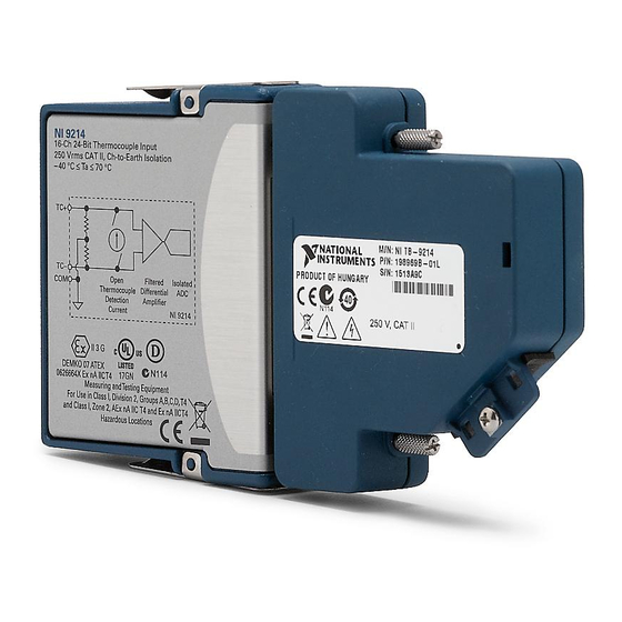
National Instruments NI 9214 Operating Instructions And Specifications
16-channel thermocouple input module with terminal block
Hide thumbs
Also See for NI 9214:
- Manual (11 pages) ,
- Getting started manual (22 pages) ,
- Getting started manual (22 pages)

Related Manuals for National Instruments NI 9214


Summary of Contents for National Instruments NI 9214
- Page 1 OPERATING INSTRUCTIONS AND SPECIFICATIONS NI 9214 with NI TB-9214 16-Channel Thermocouple Input Module with Terminal Block Français Deutsch ni.com/manuals...
- Page 2 This document describes how to use the National Instruments 9214 in conjunction with an NI TB-9214 terminal block and includes specifications for the NI 9214 and terminal assignments for the NI TB-9214. Visit and enter ni.com/info rdsoftwareversion to determine which software you need for the modules you are using.
-
Page 3: Safety Guidelines For Hazardous Voltages
Safety Guidelines Operate the NI 9214 only as described in these operating instructions. This icon denotes that the component may be Hot Surface hot. Touching this component may result in bodily injury. Safety Guidelines for Hazardous Voltages If hazardous voltages are connected to the module, take the following precautions. - Page 4 You must use the NI TB-9214 terminal block included with the NI 9214 to ensure that the terminals are not accessible. Figure 1 shows the NI TB-9214 terminal block.
-
Page 5: Safety Guidelines For Hazardous Locations
Safety Guidelines for Hazardous Locations The NI 9214 is suitable for use in Class I, Division 2, Groups A, B, C, D, T4 hazardous locations; Class I, Zone 2, AEx nA IIC T4, and Ex nA IIC T4 hazardous locations; and nonhazardous locations only. -
Page 6: Electromagnetic Compatibility Guidelines
II 3G and is suitable for use in Zone 2 hazardous locations, in ambient temperatures of –40 °C Ta 70 °C. If you are using the NI 9214 in Gas Group IIC hazardous locations, you must use the device in an NI chassis that has been evaluated as Ex nC IIC T4, EEx nC IIC T4, Ex nA IIC T4, or Ex nL IIC T4 equipment. -
Page 7: Special Guidelines For Marine Applications
Furthermore, any changes or modifications to the product not expressly approved by National Instruments could void your authority to operate it under your local regulatory rules. When operating this product, use shielded Caution cables and accessories. - Page 8 TC1+ TC6– TC1– TC10+ TC7+ TC2+ TC13+ TC10– TC7– TC2– TC13– TC11+ TC8+ TC3+ TC14+ TC11– TC8– TC3– TC14– TC12+ TC9+ TC4+ TC15+ TC12– TC9– TC4– TC15– Figure 2. NI TB-9214 Terminal Reference NI 9214 Operating Instructions and Specifications ni.com...
- Page 9 The NI 9214 also has two common terminals, COM, that are internally connected to the isolated ground reference of the module. A connection to COM is not necessary for most applications.
-
Page 10: Connecting The Signals
6. Route the wire through the NI TB-9214 opening. 7. Remove slack in the NI TB-9214 wiring and secure the wires by threading a zip tie through the two strain relief holes on the NI TB-9214 opening. NI 9214 Operating Instructions and Specifications ni.com... - Page 11 1 Top Cover 4 Strain Relief Holes 2 Foam Pad 5 Ground Lug 3 Terminals Figure 3. Connecting Wires to the NI TB-9214 © National Instruments Corp. NI 9214 Operating Instructions and Specifications...
- Page 12 Refer to Figure 4 for an illustration of a typical shielding configuration. Thermocouple TC– Shield Ground NI 9214 Chassis Ground Figure 4. Connecting a Shielded Thermocouple Input Signal to the NI 9214 NI 9214 Operating Instructions and Specifications ni.com...
- Page 13 Installing the NI TB-9214 Connect the NI TB-9214 to the NI 9214 front connector as shown in Figure 5. Tighten the two jackscrews on the NI TB-9214 to hold it securely in place. Do not overtighten the jackscrews. Figure 5. Installing the NI TB-9214...
- Page 14 Current Multiplexer NI 9214 Figure 6. Input Circuitry for One Channel of the NI 9214 Each thermocouple channel has a programmable open thermocouple detection (OTD) circuit, which consists of a current source between the TC+ and TC– terminals. If an open thermocouple is connected to the channel, the current source forces a full-scale voltage across the terminals.
- Page 15 The channels share a common ground, COM, that is isolated from other modules in the system. The NI 9214 common-mode range is the maximum voltage allowed between any channel and COM. The NI 9214 measures the common-mode voltage level of each channel and returns a warning in the software if the signal is outside the common-mode voltage range.
- Page 16 NI 9214. For the best accuracy results, keep temperature gradients across NI 9214 terminals to a minimum, null the lead wire resistance, and enable the autozero channel. Refer to the Minimizing Thermal...
-
Page 17: Cold-Junction Temperature Measurement Accuracy
Heat dissipated by adjacent modules or other nearby heat sources can cause errors in thermocouple measurements by heating up the NI 9214 terminals to a different temperature than the cold-junction compensation sensor. The thermal gradient across the terminals can cause the terminals of different channels to be at different... - Page 18 A change in system power can happen when the system powers on, the system comes out of sleep mode, or you insert/remove modules. Refer to the warm-up time in the Specifications section for more information. NI 9214 Operating Instructions and Specifications ni.com...
- Page 19 OTD bias current. Subtract the error voltage from subsequent measurements. Visit and enter for more information ni.com/info 9214OTD about compensating for the OTD errors. © National Instruments Corp. NI 9214 Operating Instructions and Specifications...
-
Page 20: Sleep Mode
Using the Autozero Channel The NI 9214 has an internal autozero channel, which can be subtracted from each thermocouple reading to compensate for offset errors. Use of the autozero channel is optional, however the NI 9214 specifications assume that autozero is applied to every sample. -
Page 21: Specifications
Specifications The following specifications are typical for the range –40 to 70 °C unless otherwise noted. The specifications are for the NI 9214 used in conjunction with an NI TB-9214. Warm-up time ........15 minutes Input Characteristics Number of channels NI 9214........ - Page 22 Channels), or 100 S/s, whichever is smaller. Sampling faster than the maximum sample rate may result in the degradation of accuracy. † Including the autozero and cold-junction channels. Common-mode voltage range Channel-to-COM......±1.2 V min COM-to-earth ground....±250 V NI 9214 Operating Instructions and Specifications ni.com...
- Page 23 OTD on/off ..... 6 s High-resolution noise rejection (at 50 and 60 Hz) ......65 dB Overvoltage protection ..... ±30 V between any two inputs Differential input impedance .... 20 M © National Instruments Corp. NI 9214 Operating Instructions and Specifications...
- Page 24 High-resolution mode....2 V typ, 8 V max High-speed mode......15 V typ, 23 V max Offset error from source impedance with OTD enabled ..Add 0.2 V per , when source impedance >50 NI 9214 Operating Instructions and Specifications ni.com...
- Page 25 23 ± 5 °C ........0.25 °C typ –20 to 70 °C ....... 0.6 °C max –40 to 70 °C ....... 0.9 °C max MTBF ..........Contact NI for Bellcore MTBF or MIL-HDBK-217F specifications. © National Instruments Corp. NI 9214 Operating Instructions and Specifications...
-
Page 26: Temperature Measurement Accuracy
Measurement sensitivity represents the smallest change in temperature that a sensor can detect. It is a function of noise. The values assume the median of the full measurement range of the standard thermocouple sensor according to NIST Monograph 175. NI 9214 Operating Instructions and Specifications ni.com... - Page 27 0 V common-mode voltage. The tables include all measurement errors of the module and terminal block including RMS noise. The tables do not include the accuracy of the thermocouple itself. © National Instruments Corp. NI 9214 Operating Instructions and Specifications...
- Page 28 1.49 1.17 1.05 0.96 0.97 1.03 1.12 1.24 23 ± 5 °C Max, 2.79 2.12 1.76 1.78 1.96 2.24 2.59 2.99 –20 to 70 °C Max, 2.79 2.12 2.00 1.98 2.17 2.42 2.77 3.18 –40 to 70 °C NI 9214 Operating Instructions and Specifications ni.com...
- Page 29 23 ± 5 °C Max, 2.33 1.64 1.50 1.81 2.46 2.91 3.42 4.32 –20 to 70 °C Max, 2.33 1.66 1.76 2.08 2.72 3.19 3.71 4.64 –40 to 70 °C © National Instruments Corp. NI 9214 Operating Instructions and Specifications...
- Page 30 0.77 0.69 0.69 0.78 0.90 23 ± 5 °C Max, 2.59 1.77 1.38 1.41 1.60 1.96 2.37 –20 to 70 °C Max, 2.59 1.77 1.53 1.53 1.77 2.13 2.55 –40 to 70 °C NI 9214 Operating Instructions and Specifications ni.com...
- Page 31 23 ± 5 °C Max, 6.85 4.91 4.26 4.25 4.32 4.38 4.47 4.85 –20 to 70 °C Max, 6.85 4.91 4.27 4.25 4.32 4.38 4.47 4.85 –40 to 70 °C © National Instruments Corp. NI 9214 Operating Instructions and Specifications...
- Page 32 4.56 3.46 2.88 2.55 2.33 23 ± 5 °C Max, — — 10.40 6.63 5.21 4.52 4.19 4.10 –20 to 70 °C Max, — — 10.45 6.66 5.23 4.54 4.21 4.11 –40 to 70 °C NI 9214 Operating Instructions and Specifications ni.com...
- Page 33 –200 1050 1300 1550 1800 Measured Temperature ( °C ) Type B Type J/N Type K Type T/E Type R/S Figure 7. Thermocouple Error Typical (High-Res), 23 ±5 °C © National Instruments Corp. NI 9214 Operating Instructions and Specifications...
- Page 34 1550 –200 1050 1300 1800 Measured Temperature ( °C ) Type B Type J/N Type K Type T/E Type R/S Figure 8. Thermocouple Error Max (High-Res), –20 to 70 °C NI 9214 Operating Instructions and Specifications ni.com...
-
Page 35: Power Requirements
NI TB-9214 screw-terminal wiring..........20 to 30 AWG thermocouple wire with 51 mm (2 in.) of outer insulation and 5.1 mm (0.2 in.) of inner insulation stripped from the end © National Instruments Corp. NI 9214 Operating Instructions and Specifications... - Page 36 Torque for screw terminals ....0.3 N · m (2.66 lb · in.) Weight NI 9214........141 g (5.0 oz) NI TB-9214 ........ 102 g (3.6 oz) Safety Safety Voltages Connect only voltages that are within the following limits. Between any two terminals....±30 V max Isolation Channel-to-channel ....
- Page 37 115 V for U.S. or 230 V for Europe. Do not connect the NI 9214 to signals or use for Caution measurements within Measurement Categories III or IV. Hazardous Locations U.S. (UL) .......... Class I, Division 2, Groups A, B, C, D, T4;...
-
Page 38: Electromagnetic Compatibility
• EN 55011 (CISPR 11): Group 1, Class A emissions • AS/NZS CISPR 11: Group 1, Class A emissions • FCC 47 CFR Part 15B: Class A emissions • ICES-001: Class A emissions NI 9214 Operating Instructions and Specifications ni.com... -
Page 39: Online Product Certification
To obtain product certifications and the Declaration of Conformity (DoC) for this product, visit , search by ni.com/certification module number or product line, and click the appropriate link in the Certification column. © National Instruments Corp. NI 9214 Operating Instructions and Specifications... -
Page 40: Shock And Vibration
18 shocks at 6 orientations Environmental National Instruments C Series modules are intended for indoor use only but may be used outdoors if installed in a suitable enclosure. Refer to the manual for the chassis you are using for more information about meeting these specifications. -
Page 41: Environmental Management
For additional environmental information, refer to the NI and the Environment Web page at . This page ni.com/environment contains the environmental regulations and directives with which NI complies, as well as other environmental information not included in this document. © National Instruments Corp. NI 9214 Operating Instructions and Specifications... - Page 42 (For information ni.com/environment/rohs_china about China RoHS compliance, go to ni.com/ environment/rohs_china Calibration You can obtain the calibration certificate and information about calibration services for the NI 9214 at ni.com/calibration Calibration interval ......1 year NI 9214 Operating Instructions and Specifications ni.com...
-
Page 43: Where To Go For Support
Where to Go for Support The National Instruments Web site is your complete resource for technical support. At you have access to ni.com/support everything from troubleshooting and application development self-help resources to email and phone assistance from NI Application Engineers. - Page 44 Taiwan 886 02 2377 2222, Thailand 662 278 6777, Turkey 90 212 279 3031, United Kingdom 44 (0) 1635 523545 LabVIEW, National Instruments, NI, ni.com, the National Instruments corporate logo, and the Eagle logo are trademarks of National Instruments Corporation. Refer to the Trademark Information at ni.com/trademarks for other National Instruments trademarks.
Need help?
Do you have a question about the NI 9214 and is the answer not in the manual?
Questions and answers