
Related Manuals for National Instruments NI 9218


Summary of Contents for National Instruments NI 9218
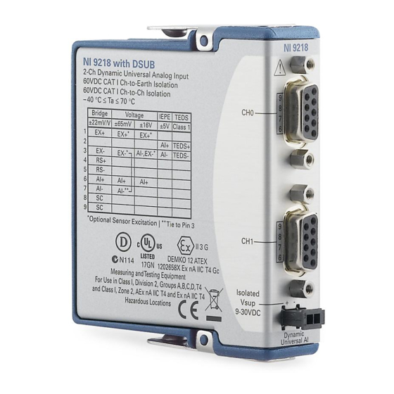
- Page 1 (217) 352-9330 | Click HERE Find the National Instruments NI 9218 at our website:...
- Page 2 GETTING STARTED GUIDE NI 9218 2 AI, 51.2 kS/s/ch Simultaneous, Universal Measurements hnology Group - Quality Instrumentation ... Guaranteed | (888) 88-SOURCE | www...
-
Page 3: Safety Guidelines
This document explains how to connect to the NI 9218. In this document, the NI 9218 with LEMO and the NI 9218 with DSUB are referred to inclusively as the NI 9218. Before you begin, complete the software and Note hardware installation procedures in your chassis documentation. - Page 4 Must use crimp contact LEMO plug (784162-01) to maintain these ratings. Ratings are invalidated if solder version is used. NI 9218 Getting Started Guide | © National Instruments | 3 hnology Group - Quality Instrumentation ... Guaranteed | (888) 88-SOURCE | www...
- Page 5 Such voltage measurements include signal levels, special equipment, limited-energy parts of equipment, circuits powered by regulated low-voltage sources, and electronics. Do not connect the NI 9218 to signals or use Caution for measurements within Measurement Categories II, III, or IV.
- Page 6 The maximum voltage between pin 2 and pin 3 on a single connector is -20 V to +30 V. NI 9218 Getting Started Guide | © National Instruments | 5 hnology Group - Quality Instrumentation ... Guaranteed | (888) 88-SOURCE | www...
- Page 7 3. The maximum excitation 6 | ni.com | NI 9218 Getting Started Guide hnology Group - Quality Instrumentation ... Guaranteed | (888) 88-SOURCE | www...
- Page 8 MAINS building installations of Measurement Categories CAT II, CAT III, or CAT IV. NI 9218 Getting Started Guide | © National Instruments | 7 hnology Group - Quality Instrumentation ... Guaranteed | (888) 88-SOURCE | www...
-
Page 9: Safety Guidelines For Hazardous Locations
Safety Guidelines for Hazardous Locations The NI 9218 is suitable for use in Class I, Division 2, Groups A, B, C, D, T4 hazardous locations; Class I, Zone 2, AEx nA IIC T4 and Ex nA IIC T4 hazardous locations; and nonhazardous locations only. - Page 10 Zone 2 hazardous locations, in ambient temperatures of -40 °C ≤ Ta ≤ 70 °C. If you are using the NI 9218 in Gas Group IIC hazardous locations, you must use the device in an NI chassis that has been evaluated as Ex nC IIC T4, Ex IIC T4, Ex nA IIC T4, or Ex nL IIC T4 equipment.
-
Page 11: Electromagnetic Compatibility Guidelines
10 | ni.com | NI 9218 Getting Started Guide hnology Group - Quality Instrumentation ... Guaranteed | (888) 88-SOURCE | www... -
Page 12: Special Conditions For Marine Applications
In order to meet the EMC requirements for Caution marine applications, install the product in a shielded NI 9218 Getting Started Guide | © National Instruments | 11 hnology Group - Quality Instrumentation ... Guaranteed | (888) 88-SOURCE | www... -
Page 13: Preparing The Environment
EMC performance is attained. Preparing the Environment Ensure that the environment in which you are using the NI 9218 meets the following specifications. Operating temperature -40 °C to 70 °C... - Page 14 NI 9218 Pinout 10 9 10 9 V– NI 9218 Getting Started Guide | © National Instruments | 13 hnology Group - Quality Instrumentation ... Guaranteed | (888) 88-SOURCE | www...
- Page 15 NI 9218 with LEMO only. Optional sensor excitation. Tie to pin 3. TEDS Class 1 data connection. TEDS Class 2 data connection. 14 | ni.com | NI 9218 Getting Started Guide hnology Group - Quality Instrumentation ... Guaranteed | (888) 88-SOURCE | www...
- Page 16 Positive remote sensing connection Negative remote sensing connection Shunt calibration connection TEDS data connection TEDS return connection NI 9218 Getting Started Guide | © National Instruments | 15 hnology Group - Quality Instrumentation ... Guaranteed | (888) 88-SOURCE | www...
-
Page 17: Measurement Types
Measurement Types The NI 9218 provides built-in support for the following measurement types. • ±16 V • ±65 mV • Full-Bridge • IEPE NI recommends using the NI 9982 screw-terminal adapter when using built-in measurement types on the NI 9218. - Page 18 VEX+ VEX- NI 9218 The NI 9218 provides optional 12 V sensor excitation. To use the 12 V excitation, connect a 9 VDC to 30 VDC power supply to Vsup, connect the excitation terminals on your sensor to EX+/ EX-, and enable 12 V excitation in your software.
- Page 19 You must connect AI- to EX- on the NI 9218. • The NI 9218 provides optional 12 V sensor excitation. To use the 12 V excitation, connect a 9 VDC to 30 VDC power supply to Vsup, connect the excitation terminals on your 18 | ni.com | NI 9218 Getting Started Guide...
- Page 20 EX+/EX-, and enable 12 V excitation in your software. Related Information NI 9982 ±65 mV Connection Pinout on page 36 NI 9218 Getting Started Guide | © National Instruments | 19 hnology Group - Quality Instrumentation ... Guaranteed | (888) 88-SOURCE | www...
- Page 21 – – NI 9218 • The NI 9218 provides 2 V excitation to loads ≥120 Ω or 3.3 V excitation to loads ≥350 Ω. • The NI 9218 provides optional connections for remote sensing (RS) and shunt calibration (SC). Remote sensing 20 | ni.com | NI 9218 Getting Started Guide...
- Page 22 Related Information NI 9982 Full-Bridge Connection Pinout on page 37 IEPE Connections NI 9218 NI 9218 Getting Started Guide | © National Instruments | 21 hnology Group - Quality Instrumentation ... Guaranteed | (888) 88-SOURCE | www...
- Page 23 • The NI 9218 provides an excitation current for each channel that powers IEPE sensors. • AI+ provides DC excitation and AI- provides the excitation return path. Related Information NI 9982 IEPE Connection Pinout on page 38 ±20 mA Connections...
- Page 24 Connecting ±20 mA signals requires the NI 9983. • The NI 9218 provides optional 12 V sensor excitation. To use the 12 V excitation, connect a 9 VDC to 30 VDC power supply to Vsup, connect the excitation terminals on your sensor to EX+/EX-, and enable 12 V excitation in your software.
- Page 25 Connecting ±60 V signals requires the NI 9987. Related Information NI 9987 Pinout on page 42 24 | ni.com | NI 9218 Getting Started Guide hnology Group - Quality Instrumentation ... Guaranteed | (888) 88-SOURCE | www...
- Page 26 Half-Bridge Connections NI 9986 NI 9218 NI 9218 Getting Started Guide | © National Instruments | 25 hnology Group - Quality Instrumentation ... Guaranteed | (888) 88-SOURCE | www...
- Page 27 • Connecting half bridges requires the NI 9986. • The NI 9218 provides 2 V excitation to half bridges of ≥240 Ω total or 3.3 V excitation to half bridges of ≥700 Ω total. • The NI 9218 provides optional connections for remote sensing (RS) and shunt calibration (SC).
- Page 28 NI recommends 2 V excitation when using a NI 9984 with 120 Ω quarter bridges and 3.3 V NI 9218 Getting Started Guide | © National Instruments | 27 hnology Group - Quality Instrumentation ... Guaranteed | (888) 88-SOURCE | www...
- Page 29 TEDS Support TEDS Class 1 sensors provide an interface for transferring information from sensors. The NI 9218 with LEMO, NI 9218 28 | ni.com | NI 9218 Getting Started Guide hnology Group - Quality Instrumentation ... Guaranteed | (888) 88-SOURCE | www...
- Page 30 NI 9218 with LEMO NI 9218 with LEMO NI 9218 with LEMO The NI 9218 with LEMO provides four pins on the Vsup connector for daisy chaining. NI 9218 Getting Started Guide | © National Instruments | 29 hnology Group - Quality Instrumentation ... Guaranteed | (888) 88-SOURCE | www...
- Page 31 NI 9218 Connection Guidelines Make sure that devices you connect to the NI 9218 are compatible with the module specifications. Custom Cabling Guidelines Observe the following guidelines when using the NI 9988 solder cup connector adapter or the LEMO crimp connector (784162-01) to create custom cables.
- Page 32 Shield Additional Additional Signals Signals Sensor NI 9988 NI 9218 NI 9218 Getting Started Guide | © National Instruments | 31 hnology Group - Quality Instrumentation ... Guaranteed | (888) 88-SOURCE | www...
- Page 33 What to Do 1. Unlock the measurement adapter housing/cover. 2. Slide the measurement adapter housing/cover to access the screw terminals. 32 | ni.com | NI 9218 Getting Started Guide hnology Group - Quality Instrumentation ... Guaranteed | (888) 88-SOURCE | www...
- Page 34 Mount the measurement adapter to a flat surface using the mounting hole on the measurement adapter and the screw. NI 9218 Getting Started Guide | © National Instruments | 33 hnology Group - Quality Instrumentation ... Guaranteed | (888) 88-SOURCE | www...
- Page 35 The ground terminals on a measurement adapter are connected to chassis ground when the measurement adapter is connected to the NI 9218 and the NI 9218 is installed in a chassis. 34 | ni.com | NI 9218 Getting Started Guide...
- Page 36 — — — AI-, — — — — — — AI-, — — NI 9982F NI 9982D/9982L NI 9218 Getting Started Guide | © National Instruments | 35 hnology Group - Quality Instrumentation ... Guaranteed | (888) 88-SOURCE | www...
- Page 37 Pins 3a and 3b are tied together on the NI 9982. Related Information ±65 mV Connections on page 18 36 | ni.com | NI 9218 Getting Started Guide hnology Group - Quality Instrumentation ... Guaranteed | (888) 88-SOURCE | www...
- Page 38 Pins 3a and 3b are tied together on the NI 9982. Related Information Full-Bridge Connections on page 20 NI 9218 Getting Started Guide | © National Instruments | 37 hnology Group - Quality Instrumentation ... Guaranteed | (888) 88-SOURCE | www...
- Page 39 NI 9982D/9982L Pins 3a and 3b are tied together on the NI 9982. Related Information IEPE Connections on page 21 38 | ni.com | NI 9218 Getting Started Guide hnology Group - Quality Instrumentation ... Guaranteed | (888) 88-SOURCE | www...
- Page 40 Pins 3a and 3b are tied together on the NI 9983. Related Information ±20 mA Connections on page 22 NI 9218 Getting Started Guide | © National Instruments | 39 hnology Group - Quality Instrumentation ... Guaranteed | (888) 88-SOURCE | www...
- Page 41 — — — — — — — — NI 9984F/9985F NI 9984D/9984L/9985D/9985L Related Information Quarter-Bridge Connections on page 27 40 | ni.com | NI 9218 Getting Started Guide hnology Group - Quality Instrumentation ... Guaranteed | (888) 88-SOURCE | www...
- Page 42 Pins 3a and 3b are tied together on the NI 9986. Related Information Half-Bridge Connections on page 25 NI 9218 Getting Started Guide | © National Instruments | 41 hnology Group - Quality Instrumentation ... Guaranteed | (888) 88-SOURCE | www...
- Page 43 Pins 3a and 3b are tied together on the NI 9987. Related Information ±60 V Connections on page 23 42 | ni.com | NI 9218 Getting Started Guide hnology Group - Quality Instrumentation ... Guaranteed | (888) 88-SOURCE | www...
-
Page 44: Where To Go Next
RELATED INFORMATION C Series Documentation Services & Resources ni.com/services cseriesdoc ni.com/info Located at ni.com/manuals Installs with the software NI 9218 Getting Started Guide | © National Instruments | 43 hnology Group - Quality Instrumentation ... Guaranteed | (888) 88-SOURCE | www... -
Page 45: Worldwide Support And Services
You can obtain the DoC for your product by visiting ni.com/certification. If your product supports calibration, you can obtain the calibration certificate for your product at ni.com/calibration. 44 | ni.com | NI 9218 Getting Started Guide hnology Group - Quality Instrumentation ... Guaranteed | (888) 88-SOURCE | www... - Page 46 NI 9218 Getting Started Guide | © National Instruments | 45 hnology Group - Quality Instrumentation ... Guaranteed | (888) 88-SOURCE | www...
- Page 47 U.S. Government Customers: The data contained in this manual was developed at private expense and is subject to the applicable limited rights and restricted data rights as set forth in FAR 52.227-14, DFAR 252.227-7014, and DFAR 252.227-7015. © 2014—2016 National Instruments. All rights reserved. 376918C-01 Mar16...
Need help?
Do you have a question about the NI 9218 and is the answer not in the manual?
Questions and answers