National Instruments NI-9213 Getting Started
Hide thumbs
Also See for NI-9213:
- Getting started manual (23 pages) ,
- Getting started (13 pages) ,
- Getting started manual (19 pages)
Table of Contents
Advertisement
Quick Links
Advertisement
Table of Contents

Related Manuals for National Instruments NI-9213


Summary of Contents for National Instruments NI-9213
- Page 1 NI-9213 Getting Started 2023-08-02...
- Page 2 NI-9213 Getting Started........
-
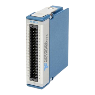
Page 3: Connector Types
The push-in type spring terminal connector is black and orange. The spring terminal connector is black. NI-9213 refers to both types unless the two types are specified. Differences between the two types of spring terminal connectors are noted by the connector color. - Page 4 TC13– TC13+ TC14+ TC14– TC15+ TC15– Table 1. Signal Descriptions Signal Description Common reference connection No connection Positive thermocouple connection Negative thermocouple connection NI-9213 (Black/Orange Connector) Pinout TC0+ TC0– TC1– TC1+ TC2+ TC2– TC3+ TC3– TC4– TC4+ TC5– TC5+ TC6–...
- Page 5 Description Common reference connection No connection Positive thermocouple connection Negative thermocouple connection Connecting Wires to the NI-9213 (Black Connector) What to Use NI-9213 spring-terminal connector ■ 0.08 mm to 1.0 mm (28 AWG to 18 AWG) copper conductor wire with ■...
-
Page 6: Connecting A Thermocouple
2. Press a wire into the open connector terminal. 3. Remove the screwdriver from the activation slot to clamp the wire into place. Connecting Wires to the NI-9213 with Push-in Style Spring Terminal (Black/Orange Connector) What to Use NI-9213 (black/orange connector) ■... -
Page 7: High-Vibration Application Connections
NI-9940 backshell kit to protect connections to the NI-9213. Common-Mode Voltage The NI-9213 common-mode range is the maximum voltage between any channel and COM. If COM is not connected, then the common-mode voltage range is the maximum voltage between any two channels. The NI-9213 measures the common- mode voltage level of each channel and returns a warning in the software if the signal is outside the common-mode voltage range. -
Page 8: Minimizing Thermal Gradients
Minimize adjacent heat sources and air flow across the terminals. ■ Keep the ambient temperature as stable as possible. ■ Make sure the NI-9213 terminals are facing forward or upward. ■ Keep the NI-9213 in a stable and consistent orientation. ■... -
Page 9: Timing Modes
Autozero Channel The NI-9213 has an internal autozero channel, which can be subtracted from each thermocouple reading to compensate for offset errors. Use of the autozero channel is optional, however the NI-9213 specifications assume that autozero is applied to every sample.
Need help?
Do you have a question about the NI-9213 and is the answer not in the manual?
Questions and answers