Table of Contents
Advertisement
Quick Links
Advertisement
Table of Contents

Related Manuals for National Instruments NI 9211


Summary of Contents for National Instruments NI 9211
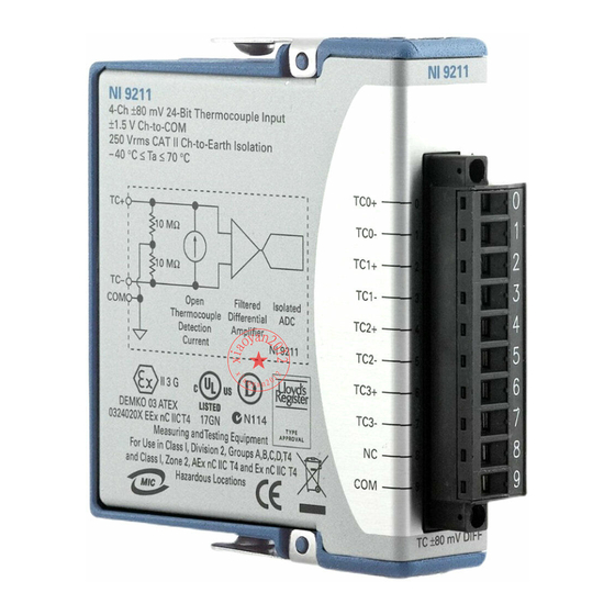
- Page 1 GETTING STARTED GUIDE NI 9211 4 TC, ±80 mV, 24 Bit, 14 S/s Aggregate...
-
Page 2: Safety Guidelines
This document explains how to connect to the NI 9211. Before you begin, complete the software and Note hardware installation procedures in your chassis documentation. The guidelines in this document are specific to Note the NI 9211. The other components in the system might not meet the same safety ratings. -
Page 3: Safety Voltages
This category refers to local-level electrical distribution, such as that provided by a standard wall outlet, for example, 115 V for U.S. or 230 V for Europe. NI 9211 Getting Started Guide | © National Instruments | 3... -
Page 4: Safety Guidelines For Hazardous Voltages
Do not connect the NI 9211 to signals or use Caution for measurements within Measurement Categories III or IV. Safety Guidelines for Hazardous Voltages If hazardous voltages are connected to the device, take the following precautions. A hazardous voltage is a voltage greater than 42.4 Vpk voltage or 60 VDC to earth ground. -
Page 5: Safety Guidelines For Hazardous Locations
Safety Guidelines for Hazardous Locations The NI 9211 is suitable for use in Class I, Division 2, Groups A, B, C, D, T4 hazardous locations; Class I, Zone 2, AEx nA IIC T4 and Ex nA IIC T4 hazardous locations; and nonhazardous locations only. - Page 6 Zone 2 hazardous locations, in ambient temperatures of -40 °C ≤ Ta ≤ 70 °C. If you are using the NI 9211 in Gas Group IIC hazardous locations, you must use the device in an NI chassis that has been evaluated as Ex nC IIC T4, Ex IIC T4, Ex nA IIC T4, or Ex nL IIC T4 equipment.
-
Page 7: Electromagnetic Compatibility Guidelines
To minimize interference with radio and television reception and prevent unacceptable performance degradation, install and use this NI 9211 Getting Started Guide | © National Instruments | 7... - Page 8 Changes or modifications not expressly Caution approved by NI could void the user's authority to operate the hardware under the local regulatory rules. 8 | ni.com | NI 9211 Getting Started Guide...
-
Page 9: Special Conditions For Marine Applications
In addition, take precautions when designing, selecting, and installing measurement probes and cables to ensure that the desired EMC performance is attained. NI 9211 Getting Started Guide | © National Instruments | 9... -
Page 10: Preparing The Environment
Preparing the Environment Ensure that the environment in which you are using the NI 9211 meets the following specifications. Operating temperature -40 °C to 70 °C (IEC 60068-2-1, IEC 60068-2-2) Operating humidity 10% RH to 90% RH, (IEC 60068-2-78) noncondensing... - Page 11 NI 9211 Pinout TC0+ TC0– TC1+ TC1– TC2+ TC2– TC3+ TC3– NI 9211 Getting Started Guide | © National Instruments | 11...
-
Page 12: Connecting A Thermocouple
Table 1. Signal Descriptions Signal Description Common reference connection to isolated ground No connection Positive thermocouple connection Negative thermocouple connection Connecting a Thermocouple You can connect a shielded thermocouple to the NI 9211. 12 | ni.com | NI 9211 Getting Started Guide... -
Page 13: Minimizing Thermal Gradients
Minimizing Thermal Gradients Changes in the ambient air temperature near the front connector or a thermocouple wire conducting heat directly to terminal junctions can cause thermal gradients. Observe the following NI 9211 Getting Started Guide | © National Instruments | 13... - Page 14 Minimize adjacent heat sources and air flow across the terminals. • Keep the ambient temperature as stable as possible. • Make sure the NI 9211 terminals are facing forward or upward. • Keep the NI 9211 in a stable and consistent orientation. •...
-
Page 15: Overvoltage Protection
High-Vibration Application Connections If your application is subject to high vibration, NI recommends that you use the NI 9932 backshell kit to protect connections to the NI 9211. NI 9211 Getting Started Guide | © National Instruments | 15... -
Page 16: Where To Go Next
NI 9211 Datasheet NI 9211 Datasheet NI-RIO Help NI-DAQmx Help LabVIEW FPGA Help LabVIEW Help RELATED INFORMATION C Series Documentation Services & Resources ni.com/services ni.com/info cseriesdoc Located at ni.com/manuals Installs with the software 16 | ni.com | NI 9211 Getting Started Guide... -
Page 17: Worldwide Support And Services
You can obtain the DoC for your product by visiting ni.com/certification. If your product supports calibration, you can obtain the calibration certificate for your product at ni.com/calibration. NI 9211 Getting Started Guide | © National Instruments | 17... - Page 18 U.S. Government Customers: The data contained in this manual was developed at private expense and is subject to the applicable limited rights and restricted data rights as set forth in FAR 52.227-14, DFAR 252.227-7014, and DFAR 252.227-7015. © 2003—2015 National Instruments. All rights reserved. 373466G-01 Dec15...
Need help?
Do you have a question about the NI 9211 and is the answer not in the manual?
Questions and answers