Advertisement
Quick Links
Operating Warnings
Adjust your flow settings carefully. Repeated false dead-end detection
indicates that the Cal value should be increased (clockwise is less sensitive).
For absolute safety always wire through the pump pressure switch.
(The pressure switch can be bypassed if absolutely necessary - the
unit will protect itself under normal conditions.)
This is a WATER PUMP controller: it will not work with air in the system.
Always prime your system before starting work. If air in the system causes
false dead-end detection, increase Cal value (clockwise is less sensitive).
Do not set the Cal value too high. Setting it higher than necessary
places extra strain on both the pump and the controller in a dead
end situation. This can result in damage to both the pump and
your controller.
Specification
Supply Voltage
Maximum Current
Typical Drive Current
Enclosure Material
Water Resistance
Dimensions
Working Temperature
DISCLAIMER
THE MANUFACTURER RESERVES THE RIGHT TO MAKE CHANGES TO ANY PRODUCT HEREIN TO IMPROVE
RELIABILITY, FUNCTION OR DESIGN. THE MANUFACTURER DOES NOT ASSUME ANY LIABILITY ARISING
OUT OF THE APPLICATION OR USE OF ANY PRODUCT OR CIRCUIT DESCRIBED HEREIN.
For more information and videos on how to use Spring controllers please visit: www.springltd.co/videos
Copyright © 2019 Spring (Europe) Ltd. All rights reserved.
V11
Value
11 - 15 VDC
10A
4-5A
ABS
IP65
115 x 65 x 40 (mm)
0 to 40 Deg C
Wiring
Pump Controller - Quick Start Guide V11 Analogue
Step 1
5
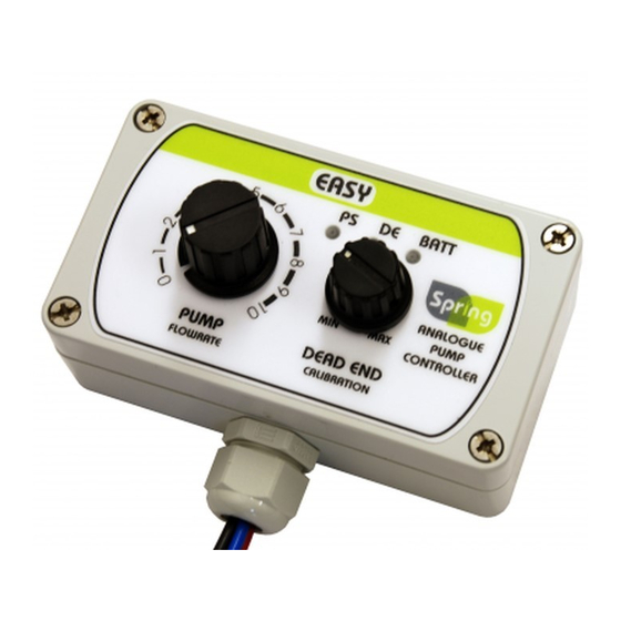
PUMP
FLOWRATE
Fuse 7.5A
Battery
+
12V
Connect the pump controller in accordance with this diagram.
NOTE: only fit the fuse once all connections are made.
Make sure correct fuse is fitted inline. Failure to do so will result in damage to the unit.
Observe correct battery polarity. Failure to do so will result in damage to the unit.
PS
DE BATT
MIN
MAX
DEAD END
CALIBRATION
Pump
Advertisement

Subscribe to Our Youtube Channel
Related Manuals for Spring V11


Summary of Contents for Spring V11
- Page 1 Make sure correct fuse is fitted inline. Failure to do so will result in damage to the unit. Observe correct battery polarity. Failure to do so will result in damage to the unit. For more information and videos on how to use Spring controllers please visit: www.springltd.co/videos Copyright © 2019 Spring (Europe) Ltd. All rights reserved.
- Page 2 V11 Analogue Step 2 Set up - Calibration Step 3 Operation V11 Analogue Connect your hose and brush to the pump. Turn on the controller by turning the PUMP FLOWRATE dial clockwise - water needs to be flowing to the brush.
Need help?
Do you have a question about the V11 and is the answer not in the manual?
Questions and answers