
Related Manuals for AEMC instruments 4620


Summary of Contents for AEMC instruments 4620
- Page 1 4620 ■ DIGITAL GROUND RESISTANCE AND SOIL 4630 RESISTIVITY TESTERS User Manual 1.800.561.8187 information@itm.com www. .com...
- Page 2 1.800.561.8187 information@itm.com www. .com...
- Page 3 1.1 International Electrical Symbols..........4 ........4 ............4 ..............5 ....6 .......7 ......8 ..............9 ...............9 ...........9 ............9 ....................................3.1 Electrical ................. 11 ................12 3.3 Environmental.................13 ..................13 ................13 ..........14 ....16 ..17 .........17 ..............21 ........23 ..24 1.800.561.8187 information@itm.com www. .com...
- Page 4 ......26 ........28 ............28 ..........31 ............32 ..........32 ........32 ......33 ....34 5.6 How to Use 25 ....36 ..................37 6.2 Disassembly ................37 ................38 ............38 ......39 ......39 ........................................................41 ............41 Limited Warranty ................42 ................42 1.800.561.8187 information@itm.com www. .com...
- Page 5 “It should be impressed on all personnel that a lethal potential can exist between the station ground and a remote ground if a system fault involving the station ground occurs while tests are being made. Since one of the objects of tests on a station ground is the establishment of the location of an effectively remote point for both current and potential electrodes, the leads to the electrodes must be treated as though a possible potential could exist between these test leads and any point on the station ground...
- Page 6 CAT IV: CAT III: CAT II: claim. 1.800.561.8187 information@itm.com www. .com...
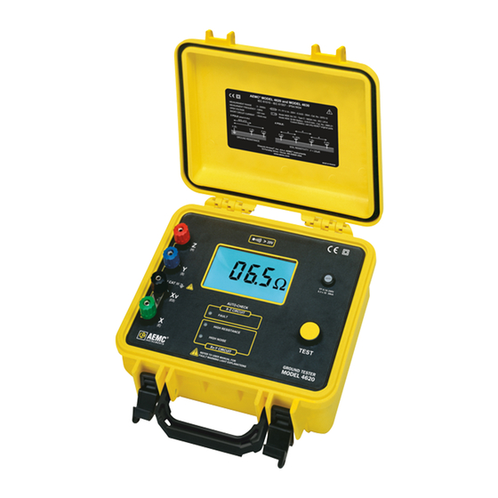
- Page 7 Ground Resistance Tester Model 4620 ......Cat. #2130.43 Includes 8 C cell batteries and user manual. Ground Resistance Tester Model 4620 Kit (150 ft) ..Cat. #2135.19 Includes ground tester, two 150 ft color-coded leads on spools (red/blue), one 30 ft...
- Page 8 Test Kit for 3-Point Testing (150 ft) ........Cat. #2135.35 Includes two 150 ft color-coded leads on spools (red/blue), one 30 ft lead (green), two T-shaped auxiliary ground electrodes, set of 5 spaded lugs, one 100 ft AEMC ® tape measure and carrying bag. Test Kit for 4-Point Testing (300 ft) ........
- Page 9 1.800.561.8187 information@itm.com www. .com...
- Page 10 1.800.561.8187 information@itm.com www. .com...
- Page 11 corrected. 1.800.561.8187 information@itm.com www. .com...
- Page 12 becomes stable. 1.800.561.8187 information@itm.com www. .com...
- Page 13 Measurement Range: Operating Frequency: Max. Auxiliary Rod Resistance: Response Time: Interference: 45 to 55%, battery power at 9.5V, auxiliary resistance at the measurement terminals = 0, no Voltage Detection Range: Frequency: Voltage Withstanding: Fuse Protection: 1.800.561.8187 information@itm.com www. .com...
- Page 14 Model 4620 Power Source: Battery Life: Low Battery Indicator: Model 4630 Power Source: Battery Life: Battery Charging: Low Battery Indicator: Connection: Display: Dimensions: Weight: Colors: Mechanical Protection: 1.800.561.8187 information@itm.com www. .com...
- Page 15 Operating Temperature: Storage Temperature: Electrical: Electromagnetic Compatibility: 1.800.561.8187 information@itm.com www. .com...
- Page 16 Figure 3 1.800.561.8187 information@itm.com www. .com...
- Page 17 Area Area 1.800.561.8187 information@itm.com www. .com...
- Page 18 Size: Figure 4 Depth: Figure 5 1.800.561.8187 information@itm.com www. .com...
- Page 19 ® ® Table 1 1.800.561.8187 information@itm.com www. .com...
- Page 20 Table 2 Table 3 1.800.561.8187 information@itm.com www. .com...
- Page 21 Figure 6 Seasonal variation of earth resistance with an electrode of 3/4" pipe in rather stony clay soil. Depth of electrode in earth is 3 ft for Curve 1, and 10 ft for Curve 2. Table 4 1.800.561.8187 information@itm.com www. .com...
- Page 22 Table 5 *Such as copper sulfate, sodium carbonate and others. Salts must be EPA or local ordinance approved prior to use. 1.800.561.8187 information@itm.com www. .com...
- Page 23 Grounding Nomograph Figure 7 scale. ® 1.800.561.8187 information@itm.com www. .com...
- Page 24 ® ® “How low in resistance should a ground be?” or less ® Code ® 1.800.561.8187 information@itm.com www. .com...
- Page 25 ® The National Electrical Code ® and NEC ® are registered trademarks of the National Fire Pro- tection Association. resistance R. 1.800.561.8187 information@itm.com www. .com...
- Page 26 Figure 8 1.800.561.8187 information@itm.com www. .com...
- Page 27 Figure 9 Figure 10 1.800.561.8187 information@itm.com www. .com...
- Page 28 Figure 11 1.800.561.8187 information@itm.com www. .com...
- Page 29 Figure 12 Figure 13 1.800.561.8187 information@itm.com www. .com...
- Page 30 Table 6 1.800.561.8187 information@itm.com www. .com...
- Page 31 Figure 14 Table 7 1.800.561.8187 information@itm.com www. .com...
- Page 32 Figure 15 1.800.561.8187 information@itm.com www. .com...
- Page 33 when an excellent ground is already available. ment. Procedure: Figure 16 1.800.561.8187 information@itm.com www. .com...
- Page 34 Figure 17 1.800.561.8187 information@itm.com www. .com...
- Page 35 installation. ® Figure 18 1.800.561.8187 information@itm.com www. .com...
- Page 36 between electrodes are identical. Example: between electrodes. A = distance between electrodes in cm = resistivity in 1.800.561.8187 information@itm.com www. .com...
- Page 37 Lay out the electrodes in a grid pattern (Figure 20) and connect to the Model 4630 as shown in Figure 19. Proceed as follows: Figure 19 1.800.561.8187 information@itm.com www. .com...
- Page 38 Figure 20 between 24.1 and 25.9 Figure 21 1.800.561.8187 information@itm.com www. .com...
- Page 39 Necessary equipment: 1.800.561.8187 information@itm.com www. .com...
- Page 40 To open the internal unit: ment. To free the display board from the cover: To free the power supply board from the bottom of the body: 1.800.561.8187 information@itm.com www. .com...
- Page 41 To achieve maximum charge capacity: 1.800.561.8187 information@itm.com www. .com...
- Page 42 is blown. 1.800.561.8187 information@itm.com www. .com...
- Page 43 For instrument repair and calibration: Ship To: 1.800.561.8187 information@itm.com www. .com...
- Page 44 ® ® Please print the online Warranty Coverage Information for your records. What AEMC Instruments will do: ® ® What you must do to return an Instrument for Warranty Repair: 1.800.561.8187 information@itm.com www. .com...
Need help?
Do you have a question about the 4620 and is the answer not in the manual?
Questions and answers