
Related Manuals for Atop CR5201B Series


Summary of Contents for Atop CR5201B Series
- Page 1 User Manual v1.0 CR5201B/SE5201B Atop Technologies, Inc. CR5201B/SE5201B Series Low-Power Wide-Area NB-IoT/Cat. M1/LTE Cat.1 Gateway User Manual v1.0 April 14 , 2023...
- Page 2 This PDF Document contains internal hyperlinks for ease of navigation. For example, click on any item listed in the Table of Contents to go to that page. Published by: Atop Technologies, Inc. 2F, No. 146, Sec. 1, Tung-Hsing Rd, 30261 Chupei City, Hsinchu County Taiwan, R.O.C.
- Page 3 CR5201B/SE5201B Important Announcement The information contained in this document is the property of Atop technologies, Inc., and is supplied for the sole purpose of operation and maintenance of Atop Technologies, Inc., products. No part of this publication is to be used for any other purposes, and it is not to be reproduced, copied, disclosed, transmitted, stored in a retrieval system, or translated into any human or computer language, in any form, by any means, in whole or in part, without the prior explicit written consent of Atop Technologies, Inc.,...
-
Page 4: Table Of Contents
User Manual v1.0 CR5201B/SE5201B Table of Contents Preface ..........................9 Purpose of the Manual ...........................9 Who Should Use This User Manual .......................9 Supported Platform ..........................9 Manufacturers’ FCC Declaration of Conformity Statement ..............9 Introduction ........................10 Overview ............................... 10 Features ............................... 11 Getting Started ........................ - Page 5 User Manual v1.0 CR5201B/SE5201B 4.12.3 System Log ............................58 4.12.4 COM log ............................... 59 4.12.5 Mobile Log ............................59 4.13 System Setup ............................61 4.13.1 Date/Time Settings ..........................61 4.13.2 Admin Settings ............................ 62 4.13.3 Firmware Upgrade ..........................63 4.13.4 Backup/Restore Configuration ......................64 4.13.5 Power Management ..........................
- Page 6 User Manual v1.0 CR5201B/SE5201B Table of Figures Figure 2.1 An Application of SE5201B with Multiple Charging Piles ................10 Figure 4.1 List of Device in Device Management Utility ....................16 Figure 4.2 Pull-down Menu of Configuration and Network..................17 Figure 4.3 Pop-up Window of Network Setting ......................
- Page 7 User Manual v1.0 CR5201B/SE5201B Figure 4.54 Certificate Upload for OpenVPN Server ....................54 Figure 4.55 Certificate Upload for OpenVPN Client ..................... 55 Figure 4.56 OpenVPN Client Status ..........................55 Figure 4.57 OpenVPN Server Status ..........................56 Figure 4.58 Log Setting Menu ............................56 Figure 4.59 Log Settings Web Page under Log Settings .....................
- Page 8 User Manual v1.0 CR5201B/SE5201B Figure 6.15 VCOM Authentication failed due to incorrect Username and/or Password ..........94 Figure 6.16 VCOM Authentication failed due to disabled VCOM Authentication on SE5201B ......... 95 Figure 6.17 Activity Panel of Serial/IP Port Monitor ..................... 96 Figure 6.18 Trace Panel of Serial/IP Port Monitor ......................
-
Page 9: Preface
1. This device may not cause harmful interference, and 2. This device must accept any interference received, including interference that may cause an undesired operation. Note: all the figures herein are intended for illustration purposes only. This software and certain features work only on certain Atop’s devices. -
Page 10: Introduction
User Manual v1.0 CR5201B/SE5201B Introduction 2.1 Overview The CR5201B/SE5201B is a Low-Power Wide-Area NB-IoT/Cat. M1/LTE Cat.1 Gateway, which acts as a gateway for communications between Ethernet (TCP/UDP) port, and SE5201B also has built-in RS-232/ RS-485 port. The information conveyed by the SE5201B model is transparent to both host computers (Ethernet) and serial devices (RS-232/ RS-485). -
Page 11: 2.2 Features
TCP Server/Client, UDP, Virtual COM and Tunneling modes supported • Remotely monitor, manage, and control industrial field devices • Configuration via Web Browser/Serial Console/Telnet Console/Atop’s Windows Utility (Device Management Utility) • Rugged metal housing with IP30 protection for wall or DIN-Rail mount •... -
Page 12: Getting Started
Noify your sales representative immediately if any of the above items is missing or damaged upon delivery. • Atop’s utility software Device View© , Serial Manager© , and Device Management Utility® are obsolete and replaced by Network Management Utility® . -
Page 13: Appearance, Front And Rear Panels
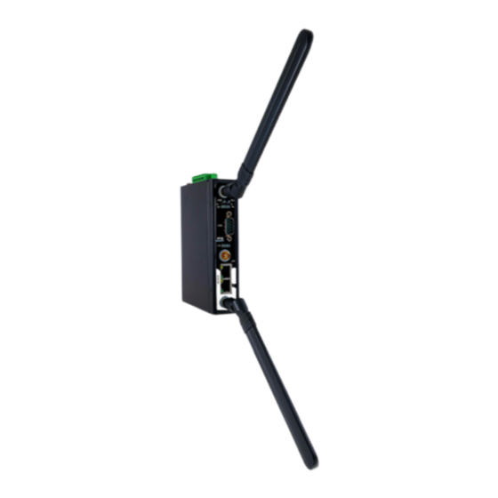
User Manual v1.0 CR5201B/SE5201B Appearance, Front and Rear Panels The following figures show CR5201B/SE5201B series device’s front and rear panels. CR5201B Front Back Side SE5201B Front (TB5) Front (DB9) Back Side... -
Page 14: First Time Installation
Before installing the device, please follow strictly all safety procedures described in the hardware installation guide supplied inside the product. Atop will not be liable for any damages to property or personal injuries resulting from the installation or overall use of the device. Do not attempt to manipulate the product in any way if unsure of the steps described here. -
Page 15: Factory Default Settings
User Manual v1.0 CR5201B/SE5201B Factory Default Settings 3.4.1 Network Default Settings The CR5201B/SE5201B Low-Power Gateway is equipped with two LAN interfaces with one default IP address. Its default network parameters are listed in Table 3.3. Table 3.3 Network Default Settings Interface Device IP Subnet Mask... -
Page 16: Configuration And Setup
Sometime the CR5201B/SE5201B device might not be in the same subnet as your PC; therefore, you will have to use Atop's utility to locate it in your virtual environment. To configure each device, first click to select the desired CR5201B/SE5201B device (default IP: 10.0.50.100) in the list of Device Management Utility© , and then click “Configuration →... -
Page 17: Figure 4.2 Pull-Down Menu Of Configuration And Network
User Manual v1.0 CR5201B/SE5201B Figure 4.2 Pull-down Menu of Configuration and Network... Figure 4.3 Pop-up Window of Network Setting You may proceed then to change the IP address to avoid any IP address conflict with other hosts on your LAN or to connect the device to your existing LAN as shown in Figure 4.3. -
Page 18: Figure 4.4 Authorization For Change Of Network Settings
User Manual v1.0 CR5201B/SE5201B Figure 4.4 Authorization for Change of Network Settings Figure 4.5 Pop-up Notification Window after Authorization Please consult your system administrator if you do not know your network’s subnet mask and gateway address. Figure 4.6 Pop-up Notification Window when there is the same IP address in the network... -
Page 19: Configuring Through Web/Cli Interface
User Manual v1.0 CR5201B/SE5201B Configuring through Web/CLI Interface Every CR5201B/SE5201B Low-Power Gateway is equipped with a built-in web server in the firmware. Therefore, the device can be accessed by using a web browser for configuring by entering the device’s IP address (default value is 192.168.1.1) in the URL field of your web browser. -
Page 20: Figure 4.9 Memu Of Configuring Web Page On Se5201B Low-Power Gateway
User Manual v1.0 CR5201B/SE5201B Figure 4.9 Memu of Configuring Web Page on SE5201B Low-Power Gateway Typically, users are more familier to use web interface for configuring the device. It is the most recommended and the most common method used for CR5201B/SE5201B Low-Power Gateway. Please go to its corresponding section for a detailed explanation. -
Page 21: Configuring Automatic Ip Assignment With Dhcp
A DHCP server can automatically assign IP addresses, Subnet Mask, and Network Gateway to LAN interface. You can simply check the “DHCP (Obtain an IP Automatically)” checkbox in the Network Setting dialog as shown in Figure 4.3 using Atop’s Device Management Utility© and then restart the device. Once restarted, the IP address will be configured automatically. -
Page 22: Network Settings
User Manual v1.0 CR5201B/SE5201B Figure 4.14 Overview Web Page (example on SE5201B-E) In details, the following information is given and divided into 2 parts (Device Information and Network Information): Device Information ◼ Model Name, as its name implies, shows the device’s model. Device Name shows a given name of the device in which the default value is the MAC address of the LAN interface. -
Page 23: Ipv4 Settings
User Manual v1.0 CR5201B/SE5201B 4.5.1 IPv4 Settings In the first submenu (IPv4 Settings), there are two sets of parameters which are LAN Settings and DNS Server that the user can input information, as shown in Figure 4.16. Note that there is another set of parameters: NAT Settings for CR5201B/SE5201B only. -
Page 24: Figure 4.17 Nat Settings Under Ipv4 Settings Web Page For Se5201B
User Manual v1.0 CR5201B/SE5201B Figure 4.17 NAT Settings under IPv4 Settings Web Page for SE5201B When NAT function is enabled on CR5201B/SE5201B , additional set of parameters which is DHCP Server field will appear as shown in Figure 4.18. The DHCP Server or Dynamic Host Configuration Protocol Server is another function on CR5201B/SE5201B under the NAT Settings. -
Page 25: Settings (Cellular Settings)
4.5.2 4G Settings (Cellular Settings) Atop’s CR5201B/SE5201B series provide the 4G settings page that allowed users to configure the cellular settings for AP (Access Point). Figure 4.20 illustrates the 4G Settings page. In the segment of 4G Information, users can manually connect/disconnect the 4G connection by clicking the Connect/Disconnect button. -
Page 26: Sim Switch
SIM Switch Atop’s SE5201B supports two SIM card slots (SIM1 and SIM2) on the chasis of the device. Users can configure the parameters for SIM2 and enabling the switching of the SIMs on this SIM Switch web page. Noted that CR5201B only supports 1 SIM card slot. -
Page 27: Figure 4.21 Sim Switch Settings Web Page
User Manual v1.0 CR5201B/SE5201B Figure 4.21 SIM Switch Settings Web Page... -
Page 28: Firewall Setting
This option allows the automatic switching of SIM card Enable Automatic Switching Disable slot The following procedures can be used to verify the cellular connection on the Atop’s CR5201B/SE5201B. 1. Check the LED display. • Check the LTE LEDs on the front panel. -
Page 29: Port Forwarding
User Manual v1.0 CR5201B/SE5201B 4.6.1 Port Forwarding Port forwarding is an application of Network Address Translation (NAT) that redirects a communication request from one address and port number combination to another while the packets are traversing a network gateway. Figure 4.23 depicts an example of port forwarding through a SE5201B device. In this example, a host or device behind the SE5201B (on the left of the figure) has a private IP address of 192.168.5.1 with port number 80. -
Page 30: Figure 4.24 Port Forwarding Web Page Of Cr5201B/Se5201B Series
User Manual v1.0 CR5201B/SE5201B Figure 4.24 Port Forwarding Web Page of CR5201B/SE5201B series Table 4.3 Description of Fields in Port Forwarding Table Field Name Description Factory Default Active This radio button allows individually enabling or disabling each entry of the port Disable forwarding configuration. -
Page 31: Ddos
4.6.2 DDoS Atop’s CR5201B/SE5201B also has built-in distributed denial-of-service (DDoS) protection mechanism. In network computing, a denial-of-service (DoS) attack is a cyber-attack that is accomplished by flooding the targeted machine such as CR5201B/SE5201B device with superfluous or fake requests in attempt to overload system and preventing some or all legitimate requests from being fulfilled. -
Page 32: Com Port Overview
User Manual v1.0 CR5201B/SE5201B 4.7.1 COM Port Overview Since details on Link Mode connectivity protocols and its settings of SE52XX series are given in Chapter 5 Link Modes and Applications, this section will only focus on the Serial Settings only. Figure 4.27 shows an example of the COM 1 Port Settings where the upper part is dedicated for Link Mode settings and the lower part is dedicated for Serial Settings. -
Page 33: Com Configuration
User Manual v1.0 CR5201B/SE5201B 4.7.2 COM Configuration Figure 4.28 excerpts the Serial Settings part of COM port settings of SE5201B. Note that these settings need to match the parameters on the serial port of the serial device. Each option is described as follows. Figure 4.28 Serial Setting Part of COM 1 Port ◼... -
Page 34: Com Configuration: Advanced Settings
User Manual v1.0 CR5201B/SE5201B 4.7.3 COM Configuration: Advanced Settings For advanced details of COM port setting, you can click on Advanced Settings button at the end of Serial Settings page which will open another web browser window as shown in Figure 4.29. Description of each option is explained as follows. - Page 35 User Manual v1.0 CR5201B/SE5201B Attention Manual Calculation of Interval Timeout The optimal “Interval timeout” depends on the application, but it must be at least larger than one-character interval within the specified baud rate. For example, assuming that the serial port is set to 1200 bps, 8 data bits, 1 stop bit, and no parity.
-
Page 36: Snmp/Alert Settings
User Manual v1.0 CR5201B/SE5201B SNMP/ALERT Settings The Simple Network Management Protocol (SNMP) is used by network management software to monitor devices in a network, to retrieve network status information of the devices, and to configure network parameters of the devices. The SNMP/ALERT Settings page showed in Figure 4.30 allows user to configure CR5201B/SE5201B device so that it can be viewed by third-party SNMP software, and allows CR5201B/SE5201B to send alert events to administrator and SNMP trap server. -
Page 37: E-Mail Settings
User Manual v1.0 CR5201B/SE5201B network management software to read/modify its information. The default CR5201B/SE5201B’s SNMP Community Strings (or passphrases) for Read Community and Write Community as shown in Figure 4.30 are “public” and “private”, respectively. Additionally, you can setup a SNMP Trap Server in the network to receive and collect all alert messages from CR5201B/SE5201B. -
Page 38: Figure 4.31 E-Mail Setting Web Page
User Manual v1.0 CR5201B/SE5201B Figure 4.31 E-mail Setting Web Page Second for the E-mail Server part, you must enter an IP address or Host Name of a Mail Server which is in your local network in the SMTP Server’s text box. Note that the maximum length of SMTP server address is 31 characters. -
Page 39: Gps
CR5201B/SE5201B 4.10 Atop’s SE5201B is equipped with GPS receiver to allows the device to aquire its current location. The Global Positioning System (GPS) is a space-based radio navigation system in which the GPS receiver requires signals from GPS’s sattelites orbiting the earth to calculate its location. Users do not need to activate the GPS module on the SE5201B since the GPS function is always enabled. -
Page 40: Ipsec
User Manual v1.0 CR5201B/SE5201B Figure 4.34 VPN Menu Structure 4.11.1 IPsec IPsec (or Internet Protocol Security) which is a network protocol suit that can establish secure and reliable communications for different application scenarios. IPsec enables data confidentiality, data integrity, data origin authentication, and antireplay. -
Page 41: Figure 4.35 An Example Of Host-To-Host Connection
User Manual v1.0 CR5201B/SE5201B CR5201B/SE5201 Figure 4.35 An Example of Host-to-Host Connection A host-to-subnet (or host-to-network) connection is mainly applied when one endpoint needs to access the other side’s sub-networks. Typical applications are employees who are travelling on business and would like to connect back to their corporate headquarters via mobile devices. -
Page 42: Figure 4.38 An Example Of Network Application Using A Subnet-To-Subnet Connection Via The Cr5201B/Se5201B And A Peer Device
User Manual v1.0 CR5201B/SE5201B CR5201B/SE5201 Figure 4.38 An example of network application using a subnet-to-subnet connection via the CR5201B/SE5201B and a peer device CR5201B/SE5201B Figure 4.39 An example of host-network application via the subnet-to-subnet connection CR5201B/SE5201B Figure 4.40 An example of host-host application via the subnet-to-subnet connection In some network configuration, there is an implementation of network address translation (NAT) on its gateway/routers. - Page 43 User Manual v1.0 CR5201B/SE5201B keys are derived. The IPsec security association (SA) is divided into two phases. In phase one, IKE creates an authenticated secure channel between CR5201B/SE5201B and its peer device, which is called the IKE Security Association. The Diffie-Hellman (DH) key agreement is always performed in this phase to create a shared secret key or DH key.
-
Page 44: Ipsec Settings
User Manual v1.0 CR5201B/SE5201B 4.11.2 IPsec Settings Figure 4.41 shows the IPsec Settings web page under the IPsec Settings menu. There are four sections on this page: General Settings, Authentication Settings, IKE Settings, and Dead Peer Detection Settings. Figure 4.41 IPsec Tunnels Web Page under IPsec Setting Menu To configure IPsec Settings, first you need to configure the General Settings section under the IPsec Settings menu. - Page 45 User Manual v1.0 CR5201B/SE5201B Dynamic: When you selected the Dynamic by choosing the Dynamic radio button, the Peer Address or the remote device IP address is not fixed or unknown. Note that when Peer Address is set to dynamic mode, the SE5201B can accept remote connection request or will be the responder. Static: On the other hand, if you know the IP address of the remote device, you can choose the ratio button for Static option and enter the IP address in the text box behind it.
-
Page 46: Table 4.4 Description Of Parameters In Ipsec Tunnels Web Page
User Manual v1.0 CR5201B/SE5201B used to encrypt this IKE communication. SE5201B supports two DH groups which are DH Group 2, which is a 1024-bit modular exponentiation group (MODP), and DH Group 5, which is a 1536-bit MODP group. Third option is the selection of Encryption Algorithm which can be either AES-128 or 3DES. This option will ◼... - Page 47 User Manual v1.0 CR5201B/SE5201B Field Name Description Default Value Remote Subnet Remote subnet can be either None (Host None (Host Only) only) or Network (IP and Netmask) Local Subnet Local subnet can be either None (Host Only) None (Host Only) or Network (IP and Netmask) Connection type Tunnel mode or Transport mode...
-
Page 48: Ipsec Status
User Manual v1.0 CR5201B/SE5201B After finishing the IPsec settings configuration, please click the Save button to save all changes that have been made. If you would like to discard any setting, please click the Cancel button. 4.11.3 IPsec Status On this web page, you can check the status of your IPsec connection between CR5201B/SE5201B and its peer device in different connection types and modes. -
Page 49: Host-To-Network Connections
User Manual v1.0 CR5201B/SE5201B Scenario: host-to-host with static peer as shown in Figure 4.44 • Check the Enable box for IPsec. • In the Peer Address field, select the Static option and enter the peer IPv4 address. Note: When peer address is entered as the static address, the CR5201B/SE5201B acts as an initiator which takes the initiative and establishes a connection. -
Page 50: Figure 4.46 Ipsec Vpn Tunnel With Host-To-Network Topology
User Manual v1.0 CR5201B/SE5201B CR5201B/SE5201 Figure 4.46 IPsec VPN Tunnel with Host-to-Network Topology Scenario: host-to-network with static peer as shown in Figure 4.47 • Check the Enable box for IPsec. • In the Peer Address field, select the Static option and enter the peer IPv4 address. Note: When peer address is entered as a static address, the CR5201B/SE5201B is an initiator which takes the initiative and establish a connection, or can be a responder waiting for connection. -
Page 51: Network-To-Network (Subnet-To-Subnet) Connections
User Manual v1.0 CR5201B/SE5201B Figure 4.48 General Settings for Host-to-Network with Dynamic Peer 4.11.7 Network-to-Network (Subnet-to-Subnet) Connections Two scenarios can also be configured for network-to-network (or subnet-to-subnet) connections: with static peer or with dynamic peer. A VPN tunnel will be created between two separate private sub-networks. Note that theCR5201B/SE5201B is the gateway to a local network in these scenarios. -
Page 52: Openvpn Setting
User Manual v1.0 CR5201B/SE5201B Figure 4.50 General Settings for Network-to-Network with Static Peer Scenario: network-to-network with dynamic peer as shown in Figure 4.51 • Check the Enable box for IPsec. • In the Peer Address field, select the Dynamic option. Note: When VPN connection is set to a peer with dynamic IP address, the CR5201B/SE5201B will act as a responder and will passively accept the connection initiated by the remote gateway. -
Page 53: Figure 4.52 Openvpn Setting
User Manual v1.0 CR5201B/SE5201B In order to configure OpenVPN, click on the VPN tab in the left side of the menu and then OpenVPN Settings. The user interface is shown in Figure 4.52. Figure 4.52 OpenVPN Setting The OpenVPN parameters are described as followings: OpenVPN: Check this box to enable OpenVPN. -
Page 54: Openvpn Keys
User Manual v1.0 CR5201B/SE5201B Hash Algorithm: This parameter specifies the Hash algorithm. There are five options available: SHA1, MD5, SHA 256, SHA 512 and Disable.When Disable option is selected, no Hash algorithm will be used. Compression: This parameter specifies whether or not the tunnel packets will be compressed. There are three options available: LZ4, LZO and Disable. -
Page 55: Openvpn Status
User Manual v1.0 CR5201B/SE5201B Figure 4.55 Certificate Upload for OpenVPN Client Click the Browse button to select your own server or client certificate and click on the Upload button. When CR5201B/SE5201B acts as an OpenVPN server, use the Export All Keys button to download all the necessary certificates including CA.crt, CA.key and the certificate and key for client side. -
Page 56: Log Settings
User Manual v1.0 CR5201B/SE5201B Figure 4.57 OpenVPN Server Status The description of each field under the Current Status of OpenVPN when it is in Server mode is as follows. Mode: This indicates the OpenVPN mode that CR5201B/SE5201B is currently running as. Local Virtual IP address: This field displays the Local virtual IP address. -
Page 57: Com Log Settings
User Manual v1.0 CR5201B/SE5201B Figure 4.59 Log Settings Web Page under Log Settings ◼ Enable Log Event to Flash: When the check box is enabled, CR5201B/SE5201B will write log events to the local flash. Otherwise, the log events would be cleared when the device restarts because they are stored in the RAM by default. -
Page 58: System Log
User Manual v1.0 CR5201B/SE5201B Log Data Contents: if this option is enabled, the COM logging function will log the content’s data that is ◼ being transmitted and received in raw bytes. If this option is disabled, COM logging function will only log the length of data to reduce system load. -
Page 59: Com Log
User Manual v1.0 CR5201B/SE5201B Figure 4.61 System Log Web Page under System Setup At the end of the System Log page, there are two hyperlinks which can be used to navigate through all records. You can click on the “Previous” link to go to the last page of the log and click on the “Next” button to go to the next page. At the top of the System Log table, there are three buttons: Refresh, Export Log, and Clear Log. -
Page 60: Figure 4.63 Mobile Log: Mobile Signal
User Manual v1.0 CR5201B/SE5201B Figure 4.63 Mobile Log: Mobile Signal Figure 4.64 Mobile Log: Mobile Temperature... -
Page 61: System Setup
User Manual v1.0 CR5201B/SE5201B 4.13 System Setup Under the System Setup menu of web interface of CR5201B/SE5201B Low-Power Gateway, you can perform a number of administration tasks for the device. Figure 4.65 lists the sub-menu under the System Setup. It consists of Date/Time Settings, Admin Settings, Firmware Upgrade, Backup/Restore Configuration, Power Management, and Ping. -
Page 62: Admin Settings
User Manual v1.0 CR5201B/SE5201B Figure 4.66 Date/Time Settings Web Page under System Setup Attention It is also important to setup Default Gateway and DNS Servers in the Network Settings properly (See Section 4.5.1), CR5201B/SE5201B can lookup DNS names and point to the proper NTP server. -
Page 63: Firmware Upgrade
Updated firmware for CR5201B/SE5201B is provided by Atop from time to time (for more information please visit Atop News & Events webpage) to fix bugs and optimize performance. It is very important that the device must NOT be turned off or powered off during the firmware upgrading, (please be patient as this whole process might take up to 5 minutes). -
Page 64: Backup/Restore Configuration
CR5201B/SE5201B model from the download tab on the CR5201B/SE5201B product page or from the Download page under the Support link on Atop’s main webpage. Then, copy the new firmware file to your local computer. Note that the firmware file is a binary file with “.dld” extension. Next, open the Web UI and select Firmware Upgrade page under the System Setup menu. -
Page 65: Figure 4.69 Backup/Restore Settings Web Page Under System Setup
User Manual v1.0 CR5201B/SE5201B Figure 4.69 Backup/Restore Settings Web Page under System Setup... -
Page 66: Power Management
User Manual v1.0 CR5201B/SE5201B 4.13.5 Power Management The CR5201B/SE5201B is able to enter two levels of standby mode to reduce power consumption when the CR5201B/SE5201B is idle. First, Sleep mode allows the CR5201B/SE5201B’s CPU to enter power saving mode and effectively reduces the power consumption to less than 2 watts. -
Page 67: Figure 4.71 Options For Schedule Power Management Mode
User Manual v1.0 CR5201B/SE5201B Figure 4.71 Options for Schedule Power Management Mode There are two trigger modes that can be chosen by selecting corresponding radio button. For Pulse trigger mode, the device will enter power saving mode or run mode per pulse. For Level trigger mode, the device will enter power saving mode for low level and run mode for high level. -
Page 68: Figure 4.72 Example Of Connecting A Switch Breaker Between Di And Dic Pins On The Se5201B
User Manual v1.0 CR5201B/SE5201B Example of Entering Hibernate Mode through DI pin in Pulse Trigger Mode Figure 4.72 shows an example of how to create a trigger to entering the Hibernate mode. Users can wire DI and DIc pins to the two pins of the switch breaker as shown in the figure. Noted that CR5201B does not support DIDO feature. -
Page 69: Figure 4.75 Location Of The Hibernate Button On The Side Of The Chasis
User Manual v1.0 CR5201B/SE5201B Example of Entering Hibernate Mode through Power Saving Button in Pulse Trigger Mode The device (SE5201B) can be put into Hibernate mode by pressing the Power Saving Button on the side of the chasis. Figure 4.75 shows the location of the Power Saving or Hibernate button. By pressing this Power Saving or Hibernate button for at least 100 ms while the system is in ready state, the device will enter the Hibernate mode. -
Page 70: Ping
User Manual v1.0 CR5201B/SE5201B 4.13.6 Ping The Web UI of CR5201B/SE5201B has an interface to call Ping which is a network diagnostic utility for testing reachability. You can use the Ping function to determine whether CR5201B/SE5201B can reach the gateway or other devices in the network. -
Page 71: Reboot
User Manual v1.0 CR5201B/SE5201B 4.14 Reboot 4.14.1 Auto Reboot CR5201B/SE5201B can be configured for automatic rebooting or Auto Reboot under the Reboot menu. To enable the Auto Reboot option, select the Reboot menu and under the Auto Reboot Settings check Enable box as shown in Figure 4.80. -
Page 72: Link Modes And Applications
User Manual v1.0 CR5201B/SE5201B Link Modes and Applications Link Mode Configuration /SE5201B series supports three different Link Modes which are TCP Server, TCP Client, and UDP. The Link Mode describes the role of SE5201B and the connection between SE5201B device and other remote devices in the network which would like to communicate with serial devices on SE5201B’s COM port(s). -
Page 73: Figure 5.3 Connection Settings For Tcp Server Link Mode
User Manual v1.0 CR5201B/SE5201B Figure 5.3 Connection Settings for TCP Server Link Mode ◼ Click on the “COM1” link on the menu frame on the left side of Web UI to go to COM 1 page as shown in Figure 5.4. Figure 5.4 TCP Server Link Mode Settings under COM 1 Page ◼... -
Page 74: Link Mode: Configure Se5201B As A Tcp Client
User Manual v1.0 CR5201B/SE5201B Pair Connection Master: This application is used when the user needs to pair two serial ▪ devices over the Ethernet network. IP Filter: This option will enable the Source IP option below. When this option is checked, SE5201B will block or filter out all other IP addresses from accessing the COM port except the one specified in the Source IP. -
Page 75: Figure 5.6 Connection Settings For Tcp Client Link Mode
User Manual v1.0 CR5201B/SE5201B Figure 5.6 shows an example of configuration setting for TCP Client Link Mode under the COM 1 page. There are additional connection settings that can be configured as shown in Figure 5.7. By selecting the TCP Client Link Mode, a TCP server program on a remote host computer should be prepared to accept a connection request from SE5201B. -
Page 76: Link Mode: Configure Se5201B In Udp
User Manual v1.0 CR5201B/SE5201B Under the TCP Client section, you will find the following options. ◼ Application: Only three communication applications are available here: RAW, Virtual COM and Pair Connection Slave in which their definitions are the same as described above in Section 5.1.1. Destination IP 1: Please specify the preferred Destination IP address of the TCP server program on the remote host in this field. -
Page 77: Figure 5.9 Connection Setting In Udp Link Mode
User Manual v1.0 CR5201B/SE5201B such as Modbus Protocol. Please do the following steps to configure connection settings of the Link Mode for each COM port. Figure 5.9 Connection Setting in UDP Link Mode Click on the “COM1” link on the menu frame on the left side of Web UI to go to COM 1 page as shown in Figure 5.10. -
Page 78: Link Mode Applications
User Manual v1.0 CR5201B/SE5201B Local Port: This field specifies the local port number for UDP Link Mode on SE5201B which it will be listening to and it can be any number between 1 and 65535. Note that typically the port number that is larger than 1024 is recommended to avoid conflicting with the well-known port numbers. -
Page 79: Tcp Server Application: Enable Rfc 2217 Through Virtual Com
Chapter 6 for necessary instructions. Please remember SE5201B’s IP address and the Local Port number configured on this page in order to enter the same information in Serial/IP Virtual COM’s Control Panel later. Note that a Serial/IP Virtual COM Redirector software is provided as a utility software by Atop Technologies. -
Page 80: Tcp Client Application: Enable Rfc 2217 Through Virtual Com
User Manual v1.0 CR5201B/SE5201B 5.2.4 TCP Client Application: Enable RFC 2217 through Virtual COM The underlying protocol of Virtual COM is based on RFC 2217 which is the Telnet COM Control Option. Therefore, it is possible to use RFC 2217 with SE5201B in the TCP Client mode. Note that the RFC 2217 allows a client, which is SE5201B in this case, to initiates a Telnet session to a remote host computer to communicate with serial device or serial (COM) program on the remote host computer. -
Page 81: Tcp Server Application: Enable Reverse Telnet
User Manual v1.0 CR5201B/SE5201B Figure 5.14 Pair Connection Slave Application in TCP Client Link Mode ◼ Follow steps in Section 5.1.2 to configure SE5201B in TCP Client Link Mode properly. ◼ Click on the drop-down list of the Application option under TCP Client section and switch to “Pair Connection Slave”... -
Page 82: Figure 5.15 Reverse Telnet Application In Tcp Server Link Mode
User Manual v1.0 CR5201B/SE5201B Figure 5.15 Reverse Telnet Application in TCP Server Link Mode ◼ Follow steps in Section 5.1.1 to configure SE5201B in TCP Server Link Mode properly. Click on the drop-down list of the Application option under TCP Server section and switch to “Reverse ◼... -
Page 83: Vcom Installation & Troubleshooting
User Manual v1.0 CR5201B/SE5201B VCOM Installation & Troubleshooting Enabling VCOM SE5201B will encapsulate control packets on top of the actual serial data when Virtual COM (VCOM) Application is enabled. This will allow the Virtual COM port in the Windows/Linux system to access SE5201B’s COM ports. Please note that Virtual COM Application can only be enabled in TCP Server Link Mode as shown in Figure 6.1 or TCP Client Link Mode as shown in Figure 6.2. -
Page 84: Figure 6.2 Enable A Virtual Com Application When Setting The Link Mode As The Tcp Client
User Manual v1.0 CR5201B/SE5201B Figure 6.2 Enable a Virtual COM Application When Setting the Link Mode as the TCP Client Virtual COM on host computer allows remote access of serial devices over TCP/IP networks through Serial/IP Virtual COM ports that work like local native COM ports. Figure 6.3 is an example of Virtual COM application diagram. In the diagram, multiple serial servers (i.e. -
Page 85: Vcom Driver Setup
To enable Virtual COM on host computer, you will require a software utility or VCOM driver software to emulate the COM port. For Windows operating system, a software utility called Serial/IP is supported by Atop to be used for this purpose. Please see discussion about the VCOM driver utility in the following subsections. -
Page 86: Limitation
User Manual v1.0 CR5201B/SE5201B product CD. The zipped package includes a binary file for installation and a manual for Linux systems. 6.1.2 Limitation The Virtual COM driver allows up to 256 Virtual COM ports in a single PC. Selection of COM port number can be allowed in the range from COM1 to COM4096. -
Page 87: Figure 6.5 Serial/Ip Tray Icon On Windows Notification Area
User Manual v1.0 CR5201B/SE5201B 2) In the Windows’ Control Panel, open the Serial/IP applet. 3) In the Windows notification area as shown in Figure 6.5, right click on the Serial/IP tray icon and click on Configure… menu to open the Serial/IP’s Control Panel. Figure 6.5 Serial/IP Tray Icon on Windows Notification Area If no Virtual COM port is selected, a “Select Ports”... -
Page 88: Figure 6.6 A Pop-Up Window For Selecting Virtual Com Ports
User Manual v1.0 CR5201B/SE5201B Figure 6.6 A Pop-up Window for Selecting Virtual COM Ports After at least one Virtual COM port is selected, the Serial/IP Control Panel window will show up as illustrated in Figure 6.7. The left side of the Control Panel window shows the list of selected Virtual COM ports. You can click on Select Ports…... -
Page 89: Configuring Vcom Ports
User Manual v1.0 CR5201B/SE5201B Figure 6.7 Serial/IP Control Panel Window 6.2.3 Configuring VCOM Ports For each VCOM port selected on the listed on the left side of the Serial/IP Control Panel, you can use the following procedures to configure that VCOM port. 1. -
Page 90: Figure 6.8 Available Options For Use Credential From In Serial/Ip Control Panel Version 4.9.10
User Manual v1.0 CR5201B/SE5201B Figure 6.8 Available Options for Use Credential From in Serial/IP Control Panel Version 4.9.10 4. Under COM Port Options box, you can enable Restore Failed Connections option by checking the box in front of it to force Virtual COM to automatically restore failed connections with the serial device server in case of unstable network connections. -
Page 91: Figure 6.9 Configuring Virtual Com 2 Port As Tcp Client
User Manual v1.0 CR5201B/SE5201B Figure 6.9 Configuring Virtual COM 2 Port as TCP Client Figure 6.10 Auto Configure (formerly Configuration Wizard) Window for COM 1... -
Page 92: Exceptions
User Manual v1.0 CR5201B/SE5201B Exceptions This section lists possible exceptions which may occur when the user tested the VCOM connection through the Auto Configure… (formerly Configuring Wizard…) button. If there is a problem with the connection, there will be error(s) or warning(s) reported in the Status and Log text boxes. The possible correction or trouble shooting hint for each exception is given in each case. -
Page 93: Figure 6.12 Error Of Client Not Licensed For This Server
“Client not licensed for this server” as shown in Figure 6.13. This means that there is a licensing issue between the serial gateway (i.e. CR5201B/SE5201B) and the Serial/IP Utility Software. Please contact Atop technical support to obtain the correct VCOM software. -
Page 94: Figure 6.14 Vcom Authentication Failed Due To Missing Username/Password
User Manual v1.0 CR5201B/SE5201B Figure 6.14 VCOM Authentication failed due to Missing Username/Password If the status reports with an exclamation mark with a message “Username and/or password incorrect” as shown in Figure 6.15. This means that the wrong username and/or password were entered and the authentication process failed. -
Page 95: Figure 6.16 Vcom Authentication Failed Due To Disabled Vcom Authentication On Se5201B
User Manual v1.0 CR5201B/SE5201B If the status reports with an exclamation mark with a message “No login/password prompts received from server” as shown in Figure 6.16. This means that the User Credentials option in the Serial/IP utility software is enabled but the VCOM Authentication option in the serial device server (i.e. -
Page 96: Using Serial/Ip Port Monitor
Using Serial/IP Port Monitor Serial/IP Port Monitor is another utility software provided for Atop’s user. It allows user to monitor the activities or status of Virtual COM port and display the exchanged serial message which is called trace over the port. -
Page 97: The Trace Panel
The pull-down menu of the Port Monitor windows allows the user to save the log and customize the capturing data of serial communication. ◼ File: To save the log file which you can send the log to Atop for further analysis if problems occurs with the Virtual COM connection, please click on File menu then click Save As. ◼... -
Page 98: Serial/Ip Advanced Settings
User Manual v1.0 CR5201B/SE5201B Notes: ◼ The Trace display covers up to 512k bytes of event data which is enough to cover a reasonably extensive tracing session. However, if the limit is reached, the trace clears and starts over. Serial/IP Advanced Settings In the Serial/IP Control Panel, you can click on the Advanced…... -
Page 99: Using Serial/Ip With A Proxy Server
User Manual v1.0 CR5201B/SE5201B 6.5.2 Using Serial/IP with a Proxy Server The Serial/IP Redirector also supports TCP network connections made through a proxy server, which may be controlling access to external networks (such as the Internet) from a private network that lacks transparent IP- based routing, such as Network Address Translation (NAT). -
Page 100: Specifications
User Manual v1.0 CR5201B/SE5201B Specifications Hardware Table 7.1 Hardware Specification System Nuvoton NUC980, Arm926EJ-S, 300MHz Flash Memory 32MB CR5201B/SE5201B DDR2 64MB EEPROM 8 KB Built-in Recessed Key (Restore to Factory Defaults) Reset Hardware built-in Watchdog Network Ethernet Interface 2x 10/100 BaseT(X) ports with RJ-45 connectors Serial Serial Interface RS-232/RS-485 Software Selectable (Default: RS-232) -
Page 101: Serial Port Pin Assignments
User Manual v1.0 CR5201B/SE5201B Serial port Pin Assignments 7.2.1 CR5201B/SE5201B Pin Assignments for Serial Interfaces DB9 to RS-232 /RS-485 connectors Figure 7.1 DB9 Pin Number Table 7.2 CR5201B/SE5201B Pin Assignment for DB9 to RS-232 /RS-485 Connector RS-232 2-Wire RS-485 Pin# Full Duplex Half Duplex Data+... -
Page 102: Cr5201B/Se5201B Pin Assignments For Terminal Block
User Manual v1.0 CR5201B/SE5201B 7.2.2 CR5201B/SE5201B Pin Assignments for Terminal Block 3-pin 2.54mm lockable Terminal Block (CR5201B only) 1 2 3 Figure 7.3 3-pin 3.81mm lockable Terminal Block Table 7.4 CR5201B Pin Assignments for Terminal Block Pin# Description F.G. 7-pin 45.72mm lockable Terminal Block (SE5201B only) 1 2 3 4 5 6 7 Figure 7.4 SE5201B Pin Assignments for Terminal Block Table 7.5 SE5201B Power Connector&... -
Page 103: Led Indicators
User Manual v1.0 CR5201B/SE5201B LED Indicators Table 7.6 Color Interpretation of LED Indicators of CR5201B/SE5201B Name Colour Status Message Steady/On Power On and Power is being supplied PWR (Power) Green Power Off and Blinking COM port is transmitting data Green COM port is not transmitting data Blinking COM port is receiving data... -
Page 104: Warranty
Products supplied by Atop Technologies Inc. are covered in this warranty for undesired performance or defects resulting from shipping, or any other event deemed to be the result of Atop Technologies Inc. mishandling. The warranty does not cover; however, equipment which has been damaged due to accident, misuse, abuse, such as: Use of incorrect power supply, connectors, or maintenance procedures ◼... - Page 105 User Manual v1.0 CR5201B/SE5201B Atop Technologies, Inc. www.atoponline.com Technical Support Contact Information www.atoponline.com/request-support Asia & Australia China Europe Jopson Li Sam Xia Alessio Longhini Tel: +886-918-694-073 Tel: +86-21-649562-31 Tel: +39-348-26-28-727 eMail: jopsonli@atop.com.tw eMail: sales@atop.com.tw eMail: alessio@atop.com.tw Germany India & SAARC...
Need help?
Do you have a question about the CR5201B Series and is the answer not in the manual?
Questions and answers