
Related Manuals for Atop MB52 Series


Summary of Contents for Atop MB52 Series
- Page 1 User Manual MB52XX Modbus Gateway V 1.0 Atop Technologies, Inc MB52XX Series Modbus Gateway User Manual V1.0 September 16 , 2019...
- Page 2 This PDF Document contains internal hyperlinks for ease of navigation. Table of Contents For example, click on any item listed in the to go to that page. Published by: Atop Technologies, Inc. 2F, No. 146, Sec. 1, Tung-Hsing Rd, 30261 Chupei City, Hsinchu County Taiwan, R.O.C.
- Page 3 V 1.0 Important Announcement The information contained in this document is the property of Atop technologies, Inc., and is supplied for the sole purpose of operation and maintenance of Atop Technologies, Inc., products. No part of this publication is to be used for any other purposes, and it is not to be reproduced, copied, disclosed, transmitted, stored in a retrieval system, or translated into any human or computer language, in any form, by any means, in whole or in part, without the prior explicit written consent of Atop Technologies, Inc.,...
-
Page 4: Table Of Contents
User Manual MB52XX Modbus Gateway V 1.0 Table of Contents Preface ..........................7 Purpose of the Manual ...........................7 Who Should Use This User Manual .......................7 Supported Platform ..........................7 Manufacturers’ FCC Declaration of Conformity Statement ..............7 Introduction .......................... 8 Overview ..............................8 Getting Started ........................ - Page 5 User Manual MB52XX Modbus Gateway V 1.0 LED Indicators ............................. 42 Software ............................... 42 Warranty ..........................43 Table of Figures Figure 2.1 Possible Network Configuration of MB52XX Series Modbus Gateway ............8 Figure 2.2 Use Cases of the MB52XX Series Modbus Gateway ..................9 Figure 4.1 List of Device in Device Management Utility ....................
- Page 6 User Manual MB52XX Modbus Gateway Preface Table 3.2 Description of Optional Accessories ......................10 Table 3.3 Network Default Setting ..........................13 Table 3.4 Modbus Default Settings ..........................13 Table 3.5 Other Default Settings ........................... 13 Table 6.1 Hardware Specification ..........................40 Table 6.2 MB5201/MB5202 Pin Assignment for DB9 to RS-232/RS-422/RS-485 Connector ........
-
Page 7: Preface
1. This device may not cause harmful interference, and 2. This device must accept any interference received, including interference that may cause an undesired operation. Note: all the figures herein are intended for illustration purposes only. This software and certain features work only on certain Atop’s devices. -
Page 8: Introduction
User Manual MB52XX Modbus Gateway Introduction Introduction 2.1 Overview The MB52XX Modbus Gateway is an industrial network device in between Modbus over Serial Line devices and computer hosts running Modbus/TCP on Ethernet network. Figure 2.1 illustrates a possible network configuration of the MB52XX Series Modbus Gateway. -
Page 9: Figure 2.2 Use Cases Of The Mb52Xx Series Modbus Gateway
User Manual MB52XX Modbus Gateway Introduction Figure 2.2 shows three different use cases of the MB52XX Series Modbus Gateway: 1) the interface between Modbus RTU/ASCII serial host to Modbus RTU/ASCII serial devices 2) the interface between Modbus/TCP over Ethernet network to Modbus RTU/ASCII serial devices 3) the interface between Modbus RTU/ASCII host connected through Serial IP over Ethernet (virtual communication port (VCOM)) to Modbus RTU/ASCII serial devices. -
Page 10: Getting Started
Notify your sales representative immediately if any of the above items is missing or damaged upon delivery. Atop’s utility software Device View© and Serial Manager© are obsolete and replaced by Device Management Utility®. Table 3.2 Description of Optional Accessories... -
Page 11: Appearance, Front And Rear Panels
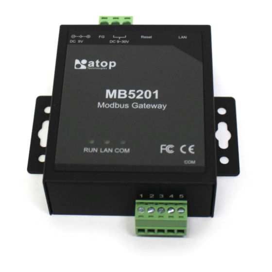
User Manual MB52XX Modbus Gateway Getting Started Appearance, Front and Rear Panels The following figures show particular MB520X series device’s front, back, side and top panels. MB5201C – Entry-Level Semi-Industrial Modbus Gateway MB5201 – Industrial 1-Port Modbus Gateway MB5202 – Industrial 2-Port Modbus Gateway... -
Page 12: First Time Installation
Before installing the device, please follow strictly all safety procedures described in the Hardware installation guide supplied inside the product. Atop will not be liable for any damages to property or personal injuries resulting from the installation or overall use of the device. Do not attempt to manipulate the product in any way if unsure of the steps described there. -
Page 13: Factory Default Settings
Other default settings are shown in the following table. Table 3.5 Other Default Settings Parameter Default Values Security User Name admin Password default SNMP SysName of SNMP atop SysLocation of SNMP Location SysContact of SNMP Contact SNMP Disable (Unchecked) Read Community Public Write Community Private SNMP Trap Server 0.0.0.0... -
Page 14: Configuration And Setup
Sometime the Modbus Gateway device might not be in the same subnet as your PC; therefore, you will have to use Atop's utility to locate it in your virtual environment. To configure each device, first click to select the desired Modbus Gateway device (default IP: 10.0.50.100) in the list of Device Management Utility©, and then click... -
Page 15: Figure 4.3 Pop-Up Window Of Network Setting
Configuration and User Manual MB52XX Modbus Gateway Setup Figure 4.3 Pop-up Window of Network Setting You may proceed then to change the IP address to avoid any IP address conflict with other hosts on your LAN or to connect the device to your existing LAN as shown in Figure 4.3. The system will prompt you for a credential to authorize the changes. -
Page 16: Configuring Through Web Interface
Configuration and User Manual MB52XX Modbus Gateway Setup Configuring through Web Interface Every MB52XX Modbus Gateway device is equipped with a built-in web server in the firmware. Therefore, the device can be accessed by using a web browser for configuring by entering the device’s IP address (default IP address is 10.0.50.100) in the URL field of your web browser. -
Page 17: Configuring Automatic Ip Assignment With Dhcp
A DHCP server can automatically assign IP addresses, Subnet Mask and Network Gateway interface. You can simply check the “DHCP (Obtain an IP Automatically)” checkbox in the Network Setting dialog as shown in Figure 4.3 using Atop’s Device Management Utility© and then restart the device. Once restarted, the IP address will be configured automatically. -
Page 18: Network Configuration
Configuration and User Manual MB52XX Modbus Gateway Setup Network Configuration In this section, IP address, Subnet Mask, Default (Network) Gateway, Domain Name System (DNS) and overall connectivity settings of Modbus Gateway device can be accessed as shown in Figure 4.8. For the LAN Interface Settings, you can check the corresponding DHCP box to obtain an IP address, Subnet Mask, and Default (Network) Gateway automatically. -
Page 19: Basic Settings
Configuration and User Manual MB52XX Modbus Gateway Setup Basic Settings In this section, the term “Modbus Gateway device” will be used to refer to the MB52XX series and the term “serial device” to refer to any Modbus device that connect to Modbus Gateway via COM, VCOM, or TCP connections. In any Modbus network, there are two types of Modbus devices: Modbus Master and Modbus Slave. -
Page 20: Operation Mode
These settings will generate a virtual Serial (VCOM) port within the Modbus Gateway device based on a TCP network connection. VCOM is a TCP connection which is encoded in an Atop Technologies’ exclusive private protocol. MB52XX series Modbus Gateway can only run as a TCP server which will be waiting for a connection request from a TCP client (a serial device). -
Page 21: Figure 4.11 Vcom Settings Web Page
Note: For Windows operating system, a Serial/IP software is required to use this feature. A restrictive Serial/IP Redirector software is installed along with Atop’s Device Management Utility®. The user can access the Serial/IP software through Virtual COM Serial/IP Tools menu. -
Page 22: Figure 4.13 Check Box For Applying The Settings To All Vcomss
Configuration and User Manual MB52XX Modbus Gateway Setup Figure 4.13 Check Box for Applying the Settings to All VCOMSs After finishing configuring the VCOM Settings, click on Save Configuration button to save all changes that have been made. A Save Successfully message will show up, then the web browser will be redirected back to the VCOM Settings page. -
Page 23: Tcp Settings
Configuration and User Manual MB52XX Modbus Gateway Setup 4.6.5 TCP Settings A device using Modbus/TCP connection, which communicates over the internet, can be set in this section. If a Modbus/TCP connection is needed, navigate to Basic Settings TCP Settings, then choose whether or not to enable TCP by checking on the “Enable”... -
Page 24: Figure 4.15 Modbus Tcp Setting Page With Tcp Master Operation Mode Selection
Configuration and User Manual MB52XX Modbus Gateway Setup At the end of the TCP Settings page shown in Figure 4.14, a list of all configured Modbus/TCP connections with TCP No., Operation Mode, Remote IP Address, TCP Port and TCP Inactivity Time Out information will appear. The user will have the ability to remove any Modbus/TCP connection settings by checking on box in front of the record of the desired TCP settings and clicking on the Remove button. -
Page 25: Slave Id Map
Configuration and User Manual MB52XX Modbus Gateway Setup After TCP Settings configuration is finished, click on Save Configuration button to save all changes that have been made. A Save Successfully message will show up, and the web browser will be redirected back to the TCP Settings page. -
Page 26: Figure 4.17 Slave Id Map Web Page With Slave Id Setting In In Offset Mode
Configuration and User Manual MB52XX Modbus Gateway Setup After finishing configuring the Slave ID Settings, click the Save Configuration button to save all changes that have been made. A Save Successfully message will show up, then the web browser will be redirected back to the Slave ID Settings page. -
Page 27: Advanced Settings
System Contact is the device administrator’s contact information. The default value is “contact”. System Name, which is by default, is the MAC address of the Modbus Gateway. The default value is “atop”. System Location is the device’s physical location. The default value is “location”. -
Page 28: Figure 4.19 Snmp Settings Web Page With Snmp Enabled And Version V1/V2C/V3
Configuration and User Manual MB52XX Modbus Gateway Setup information available for public viewing, simply flag the “Enable SNMP” checkbox and fill in your desired password string (the default string is “public”) in the Read Community field. Write Community is the field that you can specify the SNMP Write Community String which is a user ID or ... -
Page 29: Figure 4.20 Snmp Settings Web Page With Snmp Enabled And Version V1/V2C
Configuration and User Manual MB52XX Modbus Gateway Setup Figure 4.20 SNMP Settings Web Page with SNMP Enabled and Version v1/v2c Figure 4.21 SNMP Settings Web Page with SNMP Enabled and Version Only v3... -
Page 30: Modbus
Configuration and User Manual MB52XX Modbus Gateway Setup 4.7.2 Modbus In Modbus settings, it is possible select whether to enable Modbus Exception by flagging the Enable checkbox as shown in Figure 4.22. If the Modbus slave returns no response and timeout occurs, it may then be necessary for the gateway to return an exception. -
Page 31: Alert Events
Configuration and User Manual MB52XX Modbus Gateway Setup Figure 4.23 SMTP Settings Web Page 4.8.2 Alert Events In Alert Events settings, the user can configure options to have the Modbus Gateway sending out device information to alert users, administrators, or responsible personnel as shown in Figure 4.24. They can be sent out automatically. -
Page 32: Figure 4.24 Alert Events Web Page
Configuration and User Manual MB52XX Modbus Gateway Setup Figure 4.24 Alert Events Web Page The user can also set an SNMP trap by checking the Trap checkbox for each of the first three anomalies above. This will send out alerts to an SNMP Trap Server. Note that to configure SNMP Trap Server please see Section 4.7. After the Alert Events setting is complete, click on Save Configuration button to save all changes that have been made. -
Page 33: System
Configuration and User Manual MB52XX Modbus Gateway Setup System 4.9.1 Log Settings This section allows the user to change the way to report the Log. The user can save his Log Event to the flash memory of the Modbus Gateway by checking the Enable Log Event to Flash box. To specify the contents of the Log, select different Log Level by changing the pull-down menu of the Log Level. -
Page 34: Modbus Statistic
Configuration and User Manual MB52XX Modbus Gateway Setup Figure 4.27 Data Log Web Page 4.9.4 Modbus Statistic Modbus’s interface statistics are reported in this section as shown in Figure 4.28. For each interface, there is a Net_Connection or socket which is an IP address bundled with its port number (only for TCP and VCOM interfaces), a DataType of the interface (ASCII, RTU, or TCP), a Mode of the Interface (either MASTER or SLAVE), the count of received messages (RxCnt), the received bytes (RxByte), the count of transmitted message (TxCnt), and the transmitted bytes (TxByte). -
Page 35: Security
Configuration and User Manual MB52XX Modbus Gateway Setup If the Manual option is selected, select the current Date (Year, Month, Day) and Time (Hour, Minute, and Second) from their corresponding pull-down menus under the Manual Setting box. In certain region, the daylight time saving is practiced. -
Page 36: Import / Export
Configuration and User Manual MB52XX Modbus Gateway Setup as the New Password). The password is case sensitive and limited to a maximum of 8 characters. After entering all required fields, click Save Password button to save the change. After the Save Successfully message showed up, the user will be prompted with a pop-up window to enter the User name and the New Password again for verification. -
Page 37: Figure 4.31 Import/Export Web Page
Configuration and User Manual MB52XX Modbus Gateway Setup reset to a factory default setting, or simply to prevent accidental loading of incompatible old settings. The backup file could also be used to efficiently deploy multiple Modbus Gateways of similar settings by restoring the settings to the devices by importing the corresponding file. -
Page 38: Factory Default
Factory Default A return to Factory Default function is available in Atop’s MB52XX Series. To restore all parameters of the Modbus Gateway to the original factory default setting, click Set to Default and Restart button as shown in Figure 4.33. -
Page 39: Figure 4.34 Restart Web Page
Configuration and User Manual MB52XX Modbus Gateway Setup Figure 4.34 Restart Web Page... -
Page 40: Specifications
User Manual MB52XX Modbus Gateway Specifications Specifications Hardware Table 5.1 Hardware Specification System 32-bit ARM Based Flash Memory 16MB Integrated DDR2 128MB EEPROM 8 KB Reset Built-in Recessed Key (Restore to Factory Defaults) Watchdog Hardware built-in Network IEEE 802.3 10BaseT IEEE 802.3u 100BaseT(X) Ethernet Interface Auto-negotiation... -
Page 41: Serial Port Pin Assignments
User Manual MB52XX Modbus Gateway Specifications Mechanical MB5201: 65mm x 78mm x 28mm (without wall-mount part) MB5201-TB: 88.5 x 78.3 x 27.8mm (with wall-mount part) MB5201-DB: 88.5 x 84 x 27.8mm (with wall-mount part and DB9 Dimensions (W x H x D, mm) connector) MB5202: 85 mm x 77mm x 28 mm (without wall-mount part) MB5202: 108 x 77mm x 28 mm (with wall-mount part) -
Page 42: Led Indicators
User Manual MB52XX Modbus Gateway Specifications 1 x 5-pin (Male Terminal Block) for RS-232/RS-422/RS485 Connector Figure 5.2 TB5 Pin Number Table 5.3 MB5201/MB5202 Pin Assignment for TB5 to RS-232/RS-422/RS-485 Connector RS-232 RS-422/4-Wire RS-485 2-Wire RS-485 Pin# Full Duplex Full Duplex Half Duplex TxD+ Data+... -
Page 43: Warranty
Products supplied by Atop Technologies Inc. are covered in this warranty for undesired performance or defects resulting from shipping, or any other event deemed to be the result of Atop Technologies Inc. mishandling. The warranty doesn’t cover; however, equipment which has been damaged due to accident, misuse, abuse, such as: ... - Page 44 ATOP INDIA OFFICE: ATOP INDONESIA BRANCH: Abhishek Srivastava Jopson Li Head of India Sales Branch Director Atop Communication Solution(P) Ltd. Wisma Lampung Jl. No. 311, 6 Main Rd, Indiranagar, No. 40, Tomang Raya Bangalore, 560038, India Jakarta, Barat, 11430, Indonesia...
Need help?
Do you have a question about the MB52 Series and is the answer not in the manual?
Questions and answers