Sign In
Upload
Manuals
Brands
Atop Manuals
Gateway
SE5201B-DB
User Manuals: Atop SE5201B-DB IoT Gateway
Manuals and User Guides for Atop SE5201B-DB IoT Gateway. We have
1
Atop SE5201B-DB IoT Gateway manual available for free PDF download: User Manual
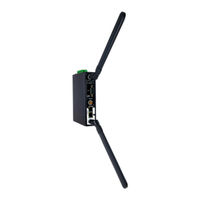
Atop SE5201B-DB User Manual (105 pages)
Low-Power Wide-Area NB-IoT/Cat. M1/LTE Cat.1 Gateway
Brand:
Atop
| Category:
Gateway
| Size: 3 MB
Table of Contents
Table of Contents
4
Preface
9
Purpose of the Manual
9
Who Should Use this User Manual
9
Supported Platform
9
Manufacturers FCC Declaration of Conformity Statement
9
Introduction
10
2.1 Overview
10
Figure 2.1 an Application of SE5201B with Multiple Charging Piles
10
2.2 Features
11
Getting Started
12
Packing List
12
Table 3.1 Packing List
12
Table 3.2 Description of Optional Accessories
12
Appearance, Front and Rear Panels
13
First Time Installation
14
Factory Default Settings
15
Network Default Settings
15
Other Default Settings
15
Table 3.3 Network Default Settings
15
Table 3.4 Security, Serial, and SNMP Default Settings
15
Configuration and Setup
16
Configuration of Network Parameters through Device Management Utility
16
Figure 4.1 List of Device in Device Management Utility
16
Figure 4.2 Pull-Down Menu of Configuration and Network
17
Figure 4.3 Pop-Up Window of Network Setting
17
Figure 4.4 Authorization for Change of Network Settings
18
Figure 4.5 Pop-Up Notification Window after Authorization
18
Figure 4.6 Pop-Up Notification Window When There Is the same IP Address in the Network
18
Configuring through Web/Cli Interface
19
Figure 4.7 Require Authentication for Accessing Web Interface
19
Figure 4.8 Overview Webpage of SE5201B Low-Power Gateway
19
Figure 4.9 Memu of Configuring Web Page on SE5201B Low-Power Gateway
20
Figure 4.10 Access Control
20
Configuring Automatic IP Assignment with DHCP
21
Web Overview
21
Figure 4.11 CLI Interface
21
Figure 4.12 Selecting DHCP Option
21
Figure 4.13 Enable DHCP Option
21
Network Settings
22
Figure 4.14 Overview Web Page (Example on SE5201B-E)
22
Figure 4.15 Three Submenus of the Network Settings Menu
22
Ipv4 Settings
23
Figure 4.16 Ipv4 Setting Within the Network Settings Menu
23
Figure 4.17 NAT Settings under Ipv4 Settings Web Page for SE5201B
24
Figure 4.18 Enabling of NAT Settings with Additional Parameters for CR5201B/SE5201B
24
Settings (Cellular Settings)
25
Figure 4.19 a Pop-Up Window Shows an Empty List of DHCP Connected Clients
25
Figure 4.20 4G Settings Web Page
25
SIM Switch
26
Table 4.1 Descriptions of 4G Settings
26
Figure 4.21 SIM Switch Settings Web Page
27
Firewall Setting
28
Figure 4.22 Firewall Setting Menu on CR5201B/SE5201B
28
Table 4.2 Description of SIM Switch's Parameters
28
Port Forwarding
29
Figure 4.23 Example of Port Forwarding through SE5201B Low-Power Gateway
29
Figure 4.24 Port Forwarding Web Page of CR5201B/SE5201B Series
30
Table 4.3 Description of Fields in Port Forwarding Table
30
Ddos
31
Serial
31
Figure 4.25 Ddos Settings Web Page
31
Figure 4.26 Serial Menu (Example on SE5201B)
31
COM Port Overview
32
Figure 4.27 COM 1 Port Settings Web Page
32
COM Configuration
33
Figure 4.28 Serial Setting Part of COM 1 Port
33
COM Configuration: Advanced Settings
34
Figure 4.29 COM 1 Advanced Settings Web Page
34
SNMP/ALERT Settings
36
Figure 4.30 Snmp/Alert Settings Web Page
36
E-Mail Settings
37
Figure 4.31 E-Mail Setting Web Page
38
Gps
39
Vpn
39
Figure 4.32 GPS Web Page
39
Figure 4.33 VPN Scenario of CR5201B/SE5201B Series
39
Ipsec
40
Figure 4.34 VPN Menu Structure
40
Figure 4.35 an Example of Host-To-Host Connection
41
Figure 4.36 Roadwarrior Application Using Host-To-Subnet Connection
41
Figure 4.37 Gateway Application Using Host-To-Subnet Connection
41
Figure 4.38 an Example of Network Application Using a Subnet-To-Subnet Connection Via the CR5201B/SE5201B and a Peer Device
42
Figure 4.39 an Example of Host-Network Application Via the Subnet-To-Subnet Connection
42
Figure 4.40 an Example of Host-Host Application Via the Subnet-To-Subnet Connection
42
Ipsec Settings
44
Figure 4.41 Ipsec Tunnels Web Page under Ipsec Setting Menu
44
Table 4.4 Description of Parameters in Ipsec Tunnels Web Page
46
Ipsec Status
48
Examples of Ipsec Settings
48
Host-To-Host Connections
48
Figure 4.42 Ipsec Status Web Page
48
Figure 4.43 Ipsec VPN Tunnel with Host-To-Host Topology
48
Host-To-Network Connections
49
Figure 4.44 General Settings for Host-To-Host with Static Peer
49
Figure 4.45 General Settings for Host-To-Host with Dynamic Peer
49
Figure 4.46 Ipsec VPN Tunnel with Host-To-Network Topology
50
Figure 4.47 General Settings for Host-To-Network with Static Peer
50
Network-To-Network (Subnet-To-Subnet) Connections
51
Figure 4.48 General Settings for Host-To-Network with Dynamic Peer
51
Figure 4.49 Ipsec VPN Tunnel with Network-To-Network Topology
51
Openvpn Setting
52
Figure 4.50 General Settings for Network-To-Network with Static Peer
52
Figure 4.51 General Settings for Network-To-Network with Dynamic Peer
52
Figure 4.52 Openvpn Setting
53
Openvpn Keys
54
Figure 4.53 Openvpn Keys Web Page
54
Figure 4.54 Certificate Upload for Openvpn Server
54
Openvpn Status
55
Figure 4.55 Certificate Upload for Openvpn Client
55
Figure 4.56 Openvpn Client Status
55
Log Settings
56
System Log Settings
56
Figure 4.57 Openvpn Server Status
56
Figure 4.58 Log Setting Menu
56
COM Log Settings
57
Figure 4.59 Log Settings Web Page under Log Settings
57
Figure 4.60 COM Log Settings Web Page under System Setup
57
System Log
58
COM Log
59
Mobile Log
59
Figure 4.61 System Log Web Page under System Setup
59
Figure 4.62 COM Datalog Web Page under Log Settings
59
Figure 4.63 Mobile Log: Mobile Signal
60
Figure 4.64 Mobile Log: Mobile Temperature
60
System Setup
61
Date/Time Settings
61
Figure 4.65 System Setup Menu
61
Admin Settings
62
Figure 4.66 Date/Time Settings Web Page under System Setup
62
Firmware Upgrade
63
Figure 4.67 Admin Settings Web Page under System Setup
63
Backup/Restore Configuration
64
Figure 4.68 Firmware Upgrade Web Page under System Setup
64
Figure 4.69 Backup/Restore Settings Web Page under System Setup
65
Power Management
66
Figure 4.70 Power Management Web Page
66
Figure 4.71 Options for Schedule Power Management Mode
67
Table 4.5 Description of Power Management Settings
67
Figure 4.72 Example of Connecting a Switch Breaker between DI and DIC Pins on the SE5201B
68
Figure 4.73 Example of LED Status While Device Is in the Hibernate Mode
68
Figure 4.74 Example of Device in Wake up State
68
Figure 4.75 Location of the Hibernate Button on the Side of the Chasis
69
Figure 4.76 Example of LED Status While Device Is in the Hibernate Mode
69
Figure 4.77 Example of Device in Wake up State
69
Ping
70
Figure 4.78 Ping Web Page under System Setup
70
Figure 4.79 Unreachable Ping Example
70
Reboot
71
Auto Reboot
71
Manual Reboot
71
Figure 4.80 Reboot Web Page with Specific Time Policy
71
Figure 4.81 Reboot Web Page with Period Time Policy
71
Link Modes and Applications
72
Link Mode Configuration
72
Link Mode: Configure SE5201B as a TCP Server
72
Figure 5.1 Link Mode Options for COM1 Port
72
Figure 5.2 CR5201B/SE5201B Is Set as a TCP Server Link Mode
72
Figure 5.3 Connection Settings for TCP Server Link Mode
73
Figure 5.4 TCP Server Link Mode Settings under COM 1 Page
73
Link Mode: Configure SE5201B as a TCP Client
74
Figure 5.5 Example of SE5201B Configured as TCP Client Link Mode
74
Figure 5.6 Connection Settings for TCP Client Link Mode
75
Figure 5.7 Setting in TCP Client Link Mode
75
Link Mode: Configure SE5201B in UDP
76
Figure 5.8 Example of CR5201B/SE5201B Configured in UDP Link Mode
76
Figure 5.9 Connection Setting in UDP Link Mode
77
Figure 5.10 UDP Link Mode Setting under COM 1 Page
77
Link Mode Applications
78
TCP Server Application: Enable Virtual COM
78
Figure 5.11 Virtual COM Application in TCP Server Link Mode
78
TCP Server Application: Enable RFC 2217 through Virtual COM
79
TCP Client Application: Enable Virtual COM
79
Figure 5.12 Virtual COM Application in TCP Client Link Mode
79
TCP Client Application: Enable RFC 2217 through Virtual COM
80
TCP Server Application: Configure SE5201B as a Pair Connection Master
80
TCP Client Application: Configure SE5201B as a Pair Connection Slave
80
Figure 5.13 Pair Connection Master Application in TCP Server Link Mode
80
TCP Server Application: Enable Reverse Telnet
81
Figure 5.14 Pair Connection Slave Application in TCP Client Link Mode
81
Figure 5.15 Reverse Telnet Application in TCP Server Link Mode
82
VCOM Installation & Troubleshooting
83
Enabling VCOM
83
Figure 6.1 Enable a Virtual COM Application When Setting the Link Mode as the TCP Server
83
Figure 6.2 Enable a Virtual COM Application When Setting the Link Mode as the TCP Client
84
VCOM Driver Setup
85
Figure 6.3 an Example Diagram of Virtual COM Application over TCP/IP Network
85
Limitation
86
Installation
86
Uninstallation
86
Enable VCOM in Serial Device Servers and Select VCOM in Windows
86
Enable VCOM in Serial Device Servers
86
Running Serial/Ip Software Utility in Windows
86
Figure 6.4 Enable Virtual COM Application for COM 1 in TCP Server Link Mode
86
Figure 6.5 Serial/Ip Tray Icon on Windows Notification Area
87
Figure 6.6 a Pop-Up Window for Selecting Virtual COM Ports
88
Configuring VCOM Ports
89
Figure 6.7 Serial/Ip Control Panel Window
89
Figure 6.8 Available Options for Use Credential from in Serial/Ip Control Panel Version 4.9.10
90
Figure 6.9 Configuring Virtual COM 2 Port as TCP Client
91
Figure 6.10 Auto Configure (Formerly Configuration Wizard) Window for COM 1
91
Exceptions
92
Figure 6.11 Timeout Warning on VCOM Connection
92
Figure 6.12 Error of Client Not Licensed for this Server
93
Figure 6.13 Licensing Issue of Serial/Ip Utility Software
93
Figure 6.14 VCOM Authentication Failed Due to Missing Username/Password
94
Figure 6.15 VCOM Authentication Failed Due to Incorrect Username And/Or Password
94
Figure 6.16 VCOM Authentication Failed Due to Disabled VCOM Authentication on SE5201B
95
Using Serial/Ip Port Monitor
96
Opening the Port Monitor
96
The Activity Panel
96
Figure 6.17 Activity Panel of Serial/Ip Port Monitor
96
The Trace Panel
97
Figure 6.18 Trace Panel of Serial/Ip Port Monitor
97
Serial/Ip Advanced Settings
98
Advanced Setting Options
98
Figure 6.19 Serial/Ip Advanced Settings Window
98
Using Serial/Ip with a Proxy Server
99
Figure 6.20 Proxy Server Tab under Serial/Ip Advanced Settings
99
Specifications
100
Hardware
100
Table 7.1 Hardware Specification
100
Serial Port Pin Assignments
101
CR5201B/SE5201B Pin Assignments for Serial Interfaces
101
Figure 7.1 DB9 Pin Number
101
Figure 7.2 TB5 Pin Number
101
Table 7.2 CR5201B/SE5201B Pin Assignment for DB9 to RS-232 /RS-485 Connector
101
Table 7.3 CR5201B/SE5201B Pin Assignment for TB5 to RS-232/ RS-485 Connector
101
CR5201B/SE5201B Pin Assignments for Terminal Block
102
Figure 7.3 3-Pin 3.81Mm Lockable Terminal Block
102
Figure 7.4 SE5201B Pin Assignments for Terminal Block
102
Table 7.4 CR5201B Pin Assignments for Terminal Block
102
Table 7.5 SE5201B Power Connector& DIO
102
LED Indicators
103
Software
103
Warranty
104
Advertisement
Advertisement
Related Products
Atop SE5201B Series
Atop SE5201B-TB
Atop SE5201B-M1
Atop SE5201B-C1
Atop SE5901 Series
Atop ABLELink SE5408
Atop SE5002D-Fs-TB
Atop ABLELink SE5404-S5is
Atop SE5908
Atop SE5901B
Atop Categories
Server
Switch
Gateway
Wireless Access Point
I/O Systems
More Atop Manuals
Login
Sign In
OR
Sign in with Facebook
Sign in with Google
Upload manual
Upload from disk
Upload from URL