Table of Contents
Advertisement
Quick Links
Advertisement
Table of Contents

Subscribe to Our Youtube Channel
Related Manuals for PhaseOne PAS 150


Summary of Contents for PhaseOne PAS 150
- Page 1 PAS 150/iX Controller MK5 Operation Guide Version: 2.0.0 Date: November 6, 2022...
- Page 2 You can contact Phase One Technical Support directly by creating a support case at https://support.phaseone.com/ Visit https://geospatial.phaseone.com/ for additional information. Copyright © 2022 Phase One. All Rights Reserved. Doc No. 80104000 Rev 2.0.0 PAS 150/iX Controller MK5 Operation Guide 06/11/2022 Page 2 of 42...
-
Page 3: Table Of Contents
PAS 150/iX Controller MK5 Operation Guide Table of Contents Table of Contents Introduction ........................................5 Scope ........................................5 Applicable Documents ................................5 System Overview ......................................6 Hardware for Single Band System ............................6 2.1.1 iX Controller MK5 ................................. 6 2.1.2 iXM-RS 150F Camera Head and Lenses ...................... - Page 4 PAS 150/iX Controller MK5 Operation Guide Table of Contents 4.6.4 Check Camera Firmware for Updates ......................32 4.6.5 Configuring GNSS/IMU Parameters ........................ 32 4.6.6 Configuring Screen Recorder Pro ........................32 4.6.7 Configuring iX Flight Pro ............................34 4.6.8 Checking the System .............................. 34 Installing the System in the Aircraft ...............................
-
Page 5: Introduction
PAS 150/iX Controller MK5 Operation Guide 1. Introduction Introduction Scope This manual describes how to install and use the PAS 150/iX Controller MK5 with iX Controller MK5 aerial system as follows: • Section 2 - System Overview • Section 3- Unboxing the System •... -
Page 6: System Overview
2. System Overview 2 System Overview The PAS 150/iX Controller MK5 is a fully integrated solution based on iXM-RS150F cameras. The aerial system comprises the camera(s), Phase One iX Controller MK5, Applanix GNSS/IMU, SOMAG mount, and the Phase One iX Suite (software). -
Page 7: Ixm-Rs 150F Camera Head And Lenses
PAS 150/iX Controller MK5 Operation Guide 2. System Overview 2.1.2 iXM-RS 150F Camera Head and Lenses The iXM-RS 150F camera is equipped with a full-frame sensor (14,204 x 10,652 pixels), and a 3.76 micrometer pixel that enables higher ground resolution from higher flight altitudes. It provides large aerial coverage resulting in higher aerial survey productivity. -
Page 8: Single-Band System Frame
PAS 150/iX Controller MK5 Operation Guide 2. System Overview 2.1.4 Single-Band System Frame The single-band system frame enables mounting the camera and the IMU. 2.1.5 Applanix GNSS/IMU The Applanix GNSS/IMU contains a precision GNSS receiver and inertial sensor components, logging capability, and interfaces for mapping sensors and flight management systems. -
Page 9: Trimble Av39 Antenna
PAS 150/iX Controller MK5 Operation Guide 2. System Overview 2.1.6 Trimble AV39 Antenna The Trimble AV39 antenna is a lightweight, TSO certified antenna that provides centimeter precision with superior phase center repeatability. The antenna is powered by the Applanix AP+ card in the iX Controller via a coaxial cable supplied with the antenna. -
Page 10: Hardware For 4-Band System
PAS 150/iX Controller MK5 Operation Guide 2. System Overview 2.1.7.2 Operator Monitor The 15.6” operator monitor provides all required information from iX Flight Pro, ensuring the operator can control all aspects of the flight, including, run selection, camera control, and data management using the touch screen. -
Page 11: Ixm-Rs150F Achromatic 50Mm Rs
PAS 150/iX Controller MK5 Operation Guide 2. System Overview 2.2.1 iXM-RS150F Achromatic 50mm RS In addition to the iXM-RS 150F camera, the 4-band system contains the iXM-RS 150F achromatic camera (P/N 72199000) to provide NIR data in the spectral range of 720nm-1000nm (4-Band System). -
Page 12: Software
In the PAS 150/iX Controller MK5 system, iX Flight Pro is pre-installed on iX Controller MK5. -
Page 13: Unboxing The System
PAS 150/iX Controller MK5 Operation Guide 3. Unboxing the System 3 Unboxing the System Verify that all parts were supplied according to the specific packing list for your system. Product Identification To enable support for your system, you must identify and record the model and serial numbers for each of the following components: •... -
Page 14: Assembling And Testing The System In The Office
PAS 150/iX Controller MK5 Operation Guide 4. Assembling and Testing the System in the Office 4 Assembling and Testing the System in the Office This section describes how to assemble the system for testing in the office. Phase One recommends assembling and testing the entire system in the office prior to transporting it and installing it in the aircraft. -
Page 15: Securing The Frame/Camera Assembly To The Csm 40 Mount (Optional)
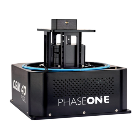
PAS 150/iX Controller MK5 Operation Guide 4. Assembling and Testing the System in the Office 2. Secure the camera to the frame using four M4x16 screws (image at right shows bottom). Tighten the screws to torque 2Nm. 4.2.2 Securing the Frame/Camera Assembly to the CSM 40 Mount (Optional) Note The frame with the camera and IMU does not have to be assembled in the mount for testing. -
Page 16: Connecting Cables To The Camera
PAS 150/iX Controller MK5 Operation Guide 4. Assembling and Testing the System in the Office 4.2.3 Connecting Cables to the Camera 1. Connect the iX Controller MK5 / Camera USB Cable (73234000) angled USB connector to the camera USB port. Tighten the screws to torque 0.25Nm. -
Page 17: Securing The Lid On The Frame
PAS 150/iX Controller MK5 Operation Guide 4. Assembling and Testing the System in the Office 4.2.4 Securing the Lid on the Frame 1. Secure the lid to the top of the frame using 9 M4x10 screws. Tighten the screws to torque 2Nm. -
Page 18: Connecting A Single-Band System
2. Place the antenna outside an open window in full view of the sky. PAS 150/iX Controller MK5 Single-Band System Connection Details Order Description Connects to... - Page 19 PAS 150/iX Controller MK5 Operation Guide 4. Assembling and Testing the System in the Office Order Description Connects to 75021000 Power, Video HDMI, USB harness • Pilot monitor (power, video - includes USB signal) • iX Controller AUX1 ports (power); DP (video);...
- Page 20 PAS 150/iX Controller MK5 Operation Guide 4. Assembling and Testing the System in the Office Single-Band System and Power Connections Page 20 of 42...
-
Page 21: Assembling A 4-Band System
PAS 150/iX Controller MK5 Operation Guide 4. Assembling and Testing the System in the Office Monitor and Keyboard Connections (Single and 4-Band Systems) 4.3 Assembling a 4-Band System The 4-Band system is preassembled in a frame. 4.3.1 Connecting the 4-Band System Note •... - Page 22 PAS 150/iX Controller MK5 Operation Guide 4. Assembling and Testing the System in the Office PAS 150/iX Controller MK5 4-Band System Connection Details Order Description Connects to 75028000 PAS Power cable • Aircraft Power Source (add suitable connector - see 5.1.6 - Connecting the...
- Page 23 PAS 150/iX Controller MK5 Operation Guide 4. Assembling and Testing the System in the Office Order Description Connects to 75021000 Power, Video HDMI, USB harness • Pilot monitor (power, video - includes USB signal) • iX Controller AUX1 ports (power); DP (video);...
- Page 24 PAS 150/iX Controller MK5 Operation Guide 4. Assembling and Testing the System in the Office 4-Band System and Power Connections Page 24 of 42...
-
Page 25: System Dataflow
PAS 150/iX Controller MK5 Operation Guide 4. Assembling and Testing the System in the Office 4.4 System Dataflow The following table details the dataflow for a PAS 150/iX Controller MK5 single and 4-band system. Dataflow for PAS 150/iX Controller MK5 Systems (Single and 4-Band) Cable... -
Page 26: Configuring The System
PAS 150/iX Controller MK5 Operation Guide 4. Assembling and Testing the System in the Office Note • The MAIN circuit breaker provides power to the iX Controller motherboard. • The AUXILIARY circuit breaker provides power to the six AUX1 and AUX2 LEMO power ports for distributing power to system components and is dependent on the MAIN circuit breaker. - Page 27 PAS 150/iX Controller MK5 Operation Guide 4. Assembling and Testing the System in the Office 3. Tap the pilot display, then in Display orientation, select Portrait (flipped). Note The operator monitor should remain in Landscape (flipped) mode. 4. Tap Apply.
-
Page 28: Changing The Mouse Pointer Color
PAS 150/iX Controller MK5 Operation Guide 4. Assembling and Testing the System in the Office 4.6.2 Changing the Mouse Pointer Color To increase the mouse pointer visibility on the pilot monitor: 1. In the Windows search box, type mouse pointer c and tap Change mouse pointer color. - Page 29 PAS 150/iX Controller MK5 Operation Guide 4. Assembling and Testing the System in the Office Tap the inverted pointer color. Page 29 of 42...
-
Page 30: Configuring Touch Monitors
PAS 150/iX Controller MK5 Operation Guide 4. Assembling and Testing the System in the Office 4.6.3 Configuring Touch Monitors 1. In the Windows search box, type calibrate and tap Calibrate the screen for pen or touch input. Page 30 of 42... - Page 31 PAS 150/iX Controller MK5 Operation Guide 4. Assembling and Testing the System in the Office 2. On the Display tab, tap Setup. 3. Follow the instructions that appear on the monitors. 4. Tap OK. Page 31 of 42...
-
Page 32: Check Camera Firmware For Updates
PAS 150/iX Controller MK5 Operation Guide 4. Assembling and Testing the System in the Office 5. Test the configuration on each monitor by: tap and dragging. The blue frame created by your finger should appear only on the monitor you are touching. - Page 33 PAS 150/iX Controller MK5 Operation Guide 4. Assembling and Testing the System in the Office 2. Verify that the following icons are active (each icon has a blue circle around it): Include Cursor Include Mouse Clicks Include KeyStrokes 3.
-
Page 34: Configuring Ix Flight Pro
PAS 150/iX Controller MK5 Operation Guide 4. Assembling and Testing the System in the Office 5. Tap Record | Stop. 6. Tap minimize. 4.6.7 Configuring iX Flight Pro 1. In iX Flight Pro, configure System Settings and Camera Settings as described in the iX Flight Pro Operation Guide. -
Page 35: Installing The System In The Aircraft
PAS 150/iX Controller MK5 Operation Guide 5. Installing the System in the Aircraft 5 Installing the System in the Aircraft This section describes how to perform a typical system installation in an aircraft. The following aircraft installation procedure assumes the system was previously assembled Note and tested in the office as described in Section 4 - Assembling and Testing the System. -
Page 36: Installing The Pilot Monitor
PAS 150/iX Controller MK5 Operation Guide 5. Installing the System in the Aircraft 5.1.4 Installing the Pilot Monitor 1. Mount the pilot monitor. A suggested method is using a proper mount with a suction cup. 5.1.5 Installing the Operator Monitor 1. -
Page 37: Connecting The System To The Aircraft Power Source
10 A Note The PAS 150/iX Controller MK5 should be connected to a 28 VDC supply. Installation on an aircraft with a 12 VDC power system is not approved unless special measures are taken to provide the PAS 150/iX Controller MK5 with 28 VDC supply. -
Page 38: Recommended Flight Operation Procedure
PAS 150/iX Controller MK5 Operation Guide 6. Recommended Flight Operation Procedure 6 Recommended Flight Operation Procedure 1. Follow the recommended flight operation procedure as described in the iX Flight Pro Operation Guide. Page 38 of 42... -
Page 39: Post Flight Operations
PAS 150/iX Controller MK5 Operation Guide 7. Post Flight Operations 7 Post Flight Operations 1. Follow the recommended post flight operations as described in the iX Flight Pro Operation Guide. Page 39 of 42... -
Page 40: Disassembling The System
PAS 150/iX Controller MK5 Operation Guide 8. Disassembling the System 8 Disassembling the System 1. Power switch on aircraft switches panel - verify off. 2. Power cable - disconnect from aircraft power outlet. 3. Pilot monitor and operator monitor - disconnect from the cables, remove from monitor mount and remove mounts from aircraft. -
Page 41: Troubleshooting
PAS 150/iX Controller MK5 Operation Guide 9. Troubleshooting 9 Troubleshooting The following table details how to troubleshoot common system faults. Troubleshooting System Faults Fault Probable Cause Solutions Camera not ready. No space on SSD • Change SSD storage. storage. •... -
Page 42: Technical Data
PAS 150/iX Controller MK5 Operation Guide 10. Technical Data 10 Technical Data 10.1 System Weight 10.1.1 Single-Band System The weight of the single-band system components is listed in the following table: Description Weight iXM-RS150F camera (excluding lens) 1 kg / 2.2 lb System frame 0.67 kg/1.5 lb...
Need help?
Do you have a question about the PAS 150 and is the answer not in the manual?
Questions and answers