
Related Manuals for Delta 32-326


Summary of Contents for Delta 32-326
- Page 1 IModem 32°325} (Modem32°326} PART NO. 449-01-651-0005 - 11-03-03 Copyright Lc) 2 003 Delta Machinery...
- Page 2 If you have any questions relative to a particular application, DO NOT use the machine until you have first contacted Delta to determine...
- Page 3 GLASSES. Also use face or dust mask if cutting Delta may cause damage to the machine or injury to the user operation is dusty. Everyday eyeglasses are NOT safety glasses. USE CERTIFIED SAFETY EQUIPMENT. USE THE PROPER EXTENSION CORD.
- Page 4 FAILURE TO FOLLOW THESE RULES MAY RESULT IN SERIOUS PERSONAL mNJURY. DO NOT OPERATE THIS MACHINE until it is AVOmD AWKWARD OPERAT{ONB HAND compbteHy assembbd and instaHHedaccording to POSITIONS. A sudden dip could cause a hand to move into the bit. the instructions.
- Page 5 A separate ebctdcai circuit shouM be used for your machines. This circuit shouid not be Hessthan #12 wire and shouM be protected with a 20 Amp time Hagfuse. If an extension cord is used, use oniy 3-wire extension cords which have 3- prong grounding type piugs and matching receptacb which will accept the machine's piug.
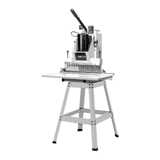
- Page 6 50 FEET NOT RECOMMENDED Fig. D Delta Models 32-325 & 32-326 are line boring machines. These line boring machines come with a large, 16"x29SA" table, which provides a large work space in front of the boring head for boring extra large boards.
-
Page 7: In This Manual
INSTRUCTIONS L ISTED AND SHOWN IN THiS MANUAL REFER TO BOTH THE 32-325 13-SPmNDLE LINE BORING MACHINE AND 32-326 13-SPmNDLE PNEUMATmC LINE BORmNG MACHINE UNLESS OTHERWISE NOTED. Fig. 2 1 - Boring Machine 2 - Fence 3 - -Fable 4 - CHear PHasfic Guard 5 - Lowering and Raising HandHe 6 - -Fable Brackets 7 - Wrench... - Page 8 32=326 13=Spindle Pneumatic Line Boring Machine 10 - Pneumatic B oringMachine 11 - Fence 12 - -Fable 13 - CHear PHastic Guard 14 - -Fable B rackets 15 - Wrench 16 - GageforAHigning Fence to DrillHead Fig. 3 18 - -Fable B racket S Hides (4) For 32-325 13-Spindle Line Boring Machine...
- Page 9 Repeat this process for the three remaining holes+ Fig. 7 FASTENING MACHINE TO A SUPPORTING SURFACE If you are using the boring machine without the accessory 32-331 steel stand, the machine IVIUST be fastened to a supporting surface using suitable hardware, not supplied by Delta+...
- Page 10 Fig.8 Fig. 9 TABLE TO MACHINE CHip the two tame sHides (A) Fig. 8, to the tame bracket (B) as shown. CHipthe remaining two tabHe sHides to the other tabHe bracket in the same manner. Center tabHe (C) Fig. 9, on the machine frame as shown.
- Page 11 FENCE TO MACHINE PHace spacer (A) Fig. 14, over hoHe (B) in tabHe bracket with Hargecountersunk end of spacer (A) in the up position. PHace a 1/4" Hockwasher (C) Fig. 14, and a 1/4" fiat washer (D) on the 1/4-20xl-1/2" hex head screw (E) and insert screw (E) up through hoHe(B) in tabHe bracket and through...
- Page 12 Fig.18 4. Withindexpins(B)Fig.18,engaged with holies in Fig.19 gage(A), H oosen tabHe H ock k nobs, o neofwhichisshown at (E),and movetabHe untiH front end of fence (F)is approximateHy 1/32"awayfromgage at point(G) o neach endofthe gage. T hentighten the tameHock k nobs(E). 5.
- Page 13 Fig.22 HEAD LOWERmNG AND RAISmNG HANDLE (For 32°325 Line Boring Machine Onmy) Remove retaining ring (A) Fig. 22, and remove con- necting pin (B). Insert end of handle (C) Fig. 23, into head assembly as shown and fasten handle in place by reassembling connecting pin that was removed in STEP 1, through hob in end of handle.
- Page 14 Fig.27 Fig. 28 4. Makecertain aircyiinderrodis retracted compbteiy intocyiinder ( E)Fig.27. Loosen iocknut(K)Fig.27,and unscrew hexendof cbvb rod(L)untiihobsiineupwith hobsinbracket ( N).Using retaining chip (A)andretaining pin(B),whichwereremoved in STEP1,fastencbvis(L) to bracket(N).Refighten bcknut (K)Fig.27. NOTE:It maybe necessary t o ioosen screws(R)Fig.28,in order to getpinto iineup withcbvis. 5.
- Page 15 3. Remove jamnut (D)Fig.31,frombottomendof air cyiinderchamp (E)andassembbair cyiinderchamp (E) Fig.32,to champ bracket(A)Fig.31, usingjamnut (D). Thread rubber f oot(F)Fig.32,ontobottomofaircyiinder champ (E)as shown.Assembbremaining air cyiinder champ t o otherchamp bracket i nthesamemanner. 4. insertred air lines (G)Fig.33, into air fittings (H) located on top of eachair cylinder c lamp(E).Pushend ofair line(G), a s farasit wiiigointofitting(H).
-
Page 16: Wrench Storage
ALIGNING BORING BITS (For 32-325 Line Boring Machine Only) Hace a fiat piece of wood (A) Fig. 37, on the tame and against the fence as shown. PuN operating handle downward until ANY ONE boring bit (B) first contacts the top of the wood surface (A). - Page 17 CONNECTING AIR TO MACHINE (For 32-326 Pneumatic Line Boring Machine Onmy} A 1/4" femaHe pipe thread (A) Fig. 43, is provided on the air fiHter for connecting the air Hineto the machine. An air suppHy of 90 psi is recommended for best resuHts and this air suppHy must not exceed 125 psi.
- Page 18 STARTING AND STOPPmNG MACHINE (For 32-326 Pneumatic Line Bering Machine Onmy} 1_ Hug the motor cord (A) Fig. 46, into outlet (B) iocated on rear of the air and ebctrb controi box as shown. 2_ Move the motor on-off switch (C) Fig. 47, to the "ON"...
- Page 19 MULTIoPOSITmON LOWERING HANDLE (For 32-325 Line Boring Machine Onmy) For extra Heverage when boring holies, the handHe (B) Fig. 50, can be pulled out as desired to increase Heverage, as shown. To move the handHe (B) out of the way when not in use, simpHy push in on handHe.
- Page 20 iMPORTANT: Before setting the iimit switch depth setting, make certain aH assemMy instructions PNEUMATmC LiNE BORING MACHINES detaibd in the in- struction manuai have been compbted. Read and under- stand "STARTING AND STOPPmNG iNSTRUCTiONS FOR PNEUMATIC LiNE BORING MACHINES", before continu- ing these instructions.
-
Page 21: Fence Stops
FENCE STOPS Two fence stops, one right (A) Fig. 58, and one Heft(B), are suppiied with your boring machine. A scab (D) is provided on the fence which has a "0" mark in the center and extends 15 inches out to the Heftand right. The stops (A) and (B) can be moved anywhere abng the fence by bosening Hockhandbs (C), moving the stops (A) and (B),... - Page 22 UNE BORING Figure 63 illustrates a typical line boring operation being performed on a workpiece. Note that the right end of the workpiece is positioned against the fence stop (A) 13 holes being bored with a 32ram center distance between each hole.
- Page 23 CORRECT OPERATING (For 32-326 Pneumatic Line Boring Machine Onmy) The following is a typbai exampb of a iine boring operation and how the ebctrb/ak controis function: Piace the workpbce (A) on the tabb and against the fence as shown in Fig. 66. Fig.
-
Page 27: Parts, Service Or Warranty Assistance
Porter-Cable ® Delta Factory Service Centers and Delta Authorized Service Stations. To obtain additional information regarding your Delta quality product or to obtain parts, service, warranty assistance, or the location of the nearest service outiet, please caii 1-800-223-7278 (in Canada caii 1-800-463-3582). - Page 28 Porter-Cable'Delta deben obtenerse poni6ndose en contacto con cualquier distribuidor Porter-Cabte'Delta, Centre de Servicio Autorizado o Centre de Servicio de F_brica Porter-Cable'Delta. Si no tiene acceso a ninguna de estas opciones, Ilame al 800-223-7278 y le dirigiran al Centre de Servicio de Fabrica Porter-Cabte'Delta mAs cercano.
Need help?
Do you have a question about the 32-326 and is the answer not in the manual?
Questions and answers