
Related Manuals for Eaton PDI WaveStar TFA STS 250-600A


Summary of Contents for Eaton PDI WaveStar TFA STS 250-600A
- Page 1 Eaton® PDI WaveStar TFA Static Transfer Switch 250 – 1200A Installation and Operation Manual p/n: P-164001113 Revision 01...
- Page 2 ToughRail Technology, and WaveStar are registered trademarks of Power Distribution Inc. All other trademarks are held by their respective owners. All other trademarks are property of their respective companies. ©Copyright 2023 Eaton, Raleigh, NC, USA. All rights reserved. No part of this document may be reproduced in any way without the express written approval of Eaton.
- Page 3 Dear Customer, On behalf of everyone at Eaton, we thank you for partnering with us, and trusting us to maintain your business continuity and preventing downtime at your facility. Our suite of backup power, power distribution and power management products are designed to protect you from a host of threats including power outages, surges, lighting strikes, and enable you to monitor and control your power infrastructure.
- Page 5 4.1.3 Mounting TFA STS on Floor Stand ......................21 4.2 Power Connections........................... 24 4.2.1 Upstream Circuit Breaker Protection ....................... 24 4.2.2 Power Sources........................... 24 4.2.3 Cable Entry/Exit..........................25 4.2.4 Top Cable Landing Compartment ......................26 Eaton PDI WaveStar TFA Static Transfer Switch Installation and Operation Manual P-164001113—Rev 01...
- Page 6 8 8 O O p p e e r r a a t t i i o o n n a a l l I I n n t t e e r r f f a a c c e e s s ....................................................6 6 1 1 Eaton PDI WaveStar TFA Static Transfer Switch Installation and Operation Manual P-164001113—Rev 01...
- Page 7 1 1 3 3 S S t t a a t t u u s s , , A A l l a a r r m m s s , , a a n n d d O O t t h h e e r r D D i i a a g g n n o o s s t t i i c c I I n n f f o o r r m m a a t t i i o o n n ....................................9 9 1 1 13.1 Points Lists............................91 13.1.1 Digital Values Screen ......................... 91 13.1.2 Analog Values screen......................... 92 Eaton PDI WaveStar TFA Static Transfer Switch Installation and Operation Manual P-164001113—Rev 01...
- Page 8 18.4 Eaton Service Contracts ........................131 18.4.1 The Service Promise ........................131 18.4.2 Preventive Maintenance ........................131 18.4.3 Eaton Provides Flexibility and Commitment ..................132 18.4.4 Time and Materials .......................... 132 viii Eaton PDI WaveStar TFA Static Transfer Switch Installation and Operation Manual P-164001113—Rev 01...
- Page 9 1 1 9 9 R R e e s s o o u u r r c c e e s s ..........................................................1 1 3 3 3 3 19.1 Glossary.............................. 133 19.2 Getting Help ............................134 19.3 Warranty and End User License Agreement ....................134 Eaton PDI WaveStar TFA Static Transfer Switch Installation and Operation Manual P-164001113—Rev 01...
- Page 10 Table of Contents Eaton PDI WaveStar TFA Static Transfer Switch Installation and Operation Manual P-164001113—Rev 01...
- Page 11 Enhanced Contractor Board (Enhanced Remote Customer Interface Board)..........57 Figure 38. Touchscreen Display: Home Screen ....................62 Figure 39. Logging in from the Home Screen ....................63 Eaton PDI WaveStar TFA Static Transfer Switch Installation and Operation Manual P-164001113—Rev 01...
-
Page 12: Table Of Contents
Figure 61. Analog Web Page........................102 Figure 62. One-Line Web Page........................103 Figure 63. Event Log Download to Spreadsheet....................104 Figure 64. Waveforms Web Page ........................ 105 Eaton PDI WaveStar TFA Static Transfer Switch Installation and Operation Manual P-164001113—Rev 01... - Page 13 STS Screen to Web Page Correspondence..................101 Table 6. Troubleshooting .......................... 109 Table 7. Digital Screen Points ........................111 Table 8. Analog Screen Points ........................116 Eaton PDI WaveStar TFA Static Transfer Switch Installation and Operation Manual P-164001113—Rev 01 xiii...
- Page 14 List of Tables Eaton PDI WaveStar TFA Static Transfer Switch Installation and Operation Manual P-164001113—Rev 01...
- Page 15 This document should not be viewed as sufficient by otherwise non-qualified personnel to operate, service, or maintain the equipment discussed. Eaton PDI WaveStar TFA Static Transfer Switch Installation and Operation Manual P-164001113—Rev 01...
- Page 16 Safety Eaton PDI WaveStar TFA Static Transfer Switch Installation and Operation Manual P-164001113—Rev 01...
- Page 17 Primary and Secondary Systems A TFA STS can be integrated with a PDU on output in a primary system or integrated with two PDUs on input in a secondary system. The TFA STS cabinet is line-and-match with Eaton PowerHub 2 and PowerPak 2 PDUs.
- Page 18 2 2 . . 2 2 . . 3 3 O O t t h h e e r r S S p p e e c c i i f f i i c c a a t t i i o o n n s s Other TFA STS specifications can be found on the TFA STS product page on the Eaton website: https://www.eaton.com/us/en-us/catalog/backup-power-ups-surge-it-power-distribution/eaton-pdi-tfa-static-...
- Page 19 System Description Figure 1. TFA STS 250-600A 3-pole, Layout Eaton PDI WaveStar TFA Static Transfer Switch Installation and Operation Manual P-164001113—Rev 01...
- Page 20 System Description Figure 2. TFA STS 800-1200A, 3-Pole, Layout Eaton PDI WaveStar TFA Static Transfer Switch Installation and Operation Manual P-164001113—Rev 01...
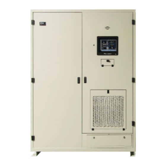
- Page 21 System Description Figure 3. TFA STS 250-600A Front and Oblique Views, Doors and Panels Closed Eaton PDI WaveStar TFA Static Transfer Switch Installation and Operation Manual P-164001113—Rev 01...
- Page 22 System Description Figure 4. Operator Interfaces: Display and Redundant Operator Interface Eaton PDI WaveStar TFA Static Transfer Switch Installation and Operation Manual P-164001113—Rev 01...
- Page 23 System Description Figure 5. TFA STS 250-600A Front View, Doors Open Eaton PDI WaveStar TFA Static Transfer Switch Installation and Operation Manual P-164001113—Rev 01...
- Page 24 System Description Figure 6. TFA STS 250-1200A 3-Pole Electrical Submittal Diagram Eaton PDI WaveStar TFA Static Transfer Switch Installation and Operation Manual P-164001113—Rev 01...
- Page 25 2 2 . . 4 4 . . 2 2 S S e e n n s s e e a a n n d d T T r r a a n n s s f f e e r r A A l l g g o o r r i i t t h h m m s s Sense algorithms detect that the active power source is going out of specification and that a transfer is required. Eaton has optimized STS sense algorithms experimentally, but algorithm parameters can be adjusted by administrators if necessary.
- Page 26 MCSW states. Keyed interlocks enforce correct coordination between MCSWs, preventing cross-currents between sides. Bypass MCSWs are mechanically interlocked to both being closed at the same time. Eaton PDI WaveStar TFA Static Transfer Switch Installation and Operation Manual P-164001113—Rev 01...
- Page 27 • The STS has two levels of operator controls and status displays. The Monitor and display is backed up by the Redundant Operator Interface (ROI). Eaton PDI WaveStar TFA Static Transfer Switch Installation and Operation Manual P-164001113—Rev 01...
- Page 28 A key is required to open doors, controlling access to the MCSWs and components. Key access is also required for the ROI. • When an STS front door is opened, the unit alarms and the alarm is logged into the Event Log. Eaton PDI WaveStar TFA Static Transfer Switch Installation and Operation Manual P-164001113—Rev 01...
- Page 29 Operation of this equipment in a residential area is likely to cause interference in which case the user at his/her own expense will be required to take whatever measures may be required to correct the interference. Eaton PDI WaveStar TFA Static Transfer Switch Installation and Operation Manual P-164001113—Rev 01...
- Page 30 System Description Eaton PDI WaveStar TFA Static Transfer Switch Installation and Operation Manual P-164001113—Rev 01...
- Page 31 The TFA STS is covered with an overhead plastic bag, shrink-wrapped, protected with corner cardboard, and strapped to a shipping skid or pallet with metal straps. You should unpack your Eaton product with the same care used in packing the product for safe and efficient delivery to your facility.
- Page 32 I I n n t t e e r r n n a a l l I I n n s s p p e e c c t t i i o o n n s s Execute the following inspections as soon as possible upon arrival of your Eaton equipment: Open the front door and check the nameplate on the cabinets to verify that the model numbers correspond with the ones specified on the bill.
- Page 33 Determine the position of the TFA STS precisely, including clearances. Attach the (2) rear floor brackets to the floor based on your measurements and dimensions in the illustration below. Installer chooses and provides floor attachment hardware. Eaton PDI WaveStar TFA Static Transfer Switch Installation and Operation Manual P-164001113—Rev 01...
- Page 34 If possible, also attach side floor brackets to the floor at their rear holes (0.75" dia. holes). Figure 9. Side Floor Brackets and Rear Brackets Eaton PDI WaveStar TFA Static Transfer Switch Installation and Operation Manual P-164001113—Rev 01...
- Page 35 Attach the left and right floor brackets to the floor stand using the hardware recommended in Figure 10 “HARDWARE STACK”. NOTE See also Figure 24, “Floor Stand Attachment Hardware.” Eaton PDI WaveStar TFA Static Transfer Switch Installation and Operation Manual P-164001113—Rev 01...
- Page 36 Installation TFA STS 250-600A Models Figure 10. Installing on Floor Stand with Side Brackets Eaton PDI WaveStar TFA Static Transfer Switch Installation and Operation Manual P-164001113—Rev 01...
- Page 37 9. You will have to reach through the cable entry/exit section to secure the brackets to the STS. NOTE See also Figure 24, “Floor Stand Attachment Hardware.” Eaton PDI WaveStar TFA Static Transfer Switch Installation and Operation Manual P-164001113—Rev 01...
- Page 38 NEC and local codes. Customer ground and phase power connections are made in the bottom left half of the unit. All connections are made from the front. Eaton PDI WaveStar TFA Static Transfer Switch Installation and Operation Manual P-164001113—Rev 01...
- Page 39 TFA STS units 250-600A can accommodate up to (8) 4" conduits per conduit panel assuming 6" dia. area per conduit. Eaton PDI WaveStar TFA Static Transfer Switch Installation and Operation Manual P-164001113—Rev 01...
- Page 40 MCSWs and the cable landing compartment from the normal TFA STS layout. Unit dimensions, power connections, and operation are otherwise the same as for standard units. Eaton PDI WaveStar TFA Static Transfer Switch Installation and Operation Manual P-164001113—Rev 01...
- Page 41 (1) position. Lugs are provided by others (specifically, by the Installer). All input and output power feeds must include an equipment grounding means as required by the NEC and local codes. Eaton PDI WaveStar TFA Static Transfer Switch Installation and Operation Manual P-164001113—Rev 01...
- Page 42 Connect phase cables to Source 1, Source 2, and Output bus plates. Source 1, Source 2, and Output each have (3) bus plates for the 3-phase connections. Each bus plate has (4) x 0.50" holes. Lugs are provided by others (specifically, by the Installer). Eaton PDI WaveStar TFA Static Transfer Switch Installation and Operation Manual P-164001113—Rev 01...
- Page 43 O O u u t t l l i i n n e e D D r r a a w w i i n n g g s s The following five (5) pages have outline drawings for TFA STS 250-600A units with Bottom Cable Landing Compartments. Submittal drawings are also available from your Eaton sales representative for units with Top Cable Landing Compartments.
- Page 44 Installation TFA STS 250-600A Models Figure 16. TFA STS 250-600A Outline Drawing 1 Eaton PDI WaveStar TFA Static Transfer Switch Installation and Operation Manual P-164001113—Rev 01...
- Page 45 Installation TFA STS 250-600A Models Figure 17. TFA STS 250-600A Outline Drawing 2 Eaton PDI WaveStar TFA Static Transfer Switch Installation and Operation Manual P-164001113—Rev 01...
- Page 46 Installation TFA STS 250-600A Models Figure 18. TFA STS 250-600A Outline Drawing 3 Eaton PDI WaveStar TFA Static Transfer Switch Installation and Operation Manual P-164001113—Rev 01...
- Page 47 Installation TFA STS 250-600A Models Figure 19. TFA STS 250-600A Outline Drawing 4 Eaton PDI WaveStar TFA Static Transfer Switch Installation and Operation Manual P-164001113—Rev 01...
- Page 48 Installation TFA STS 250-600A Models Figure 20. TFA STS 250-600A Outline Drawing 5 Eaton PDI WaveStar TFA Static Transfer Switch Installation and Operation Manual P-164001113—Rev 01...
- Page 49 Placement procedure: Determine the position of the TFA STS precisely, including clearances. Install the (3) rear floor brackets based on your measurements and dimensions in the illustration below. Eaton PDI WaveStar TFA Static Transfer Switch Installation and Operation Manual P-164001113—Rev 01...
- Page 50 Attach the side floor brackets to the floor at their front holes (0.75" dia. holes). If possible, also attach side floor brackets to the floor at their rear holes (0.75" dia. holes). Figure 21. Floor Brackets Side and Rear Eaton PDI WaveStar TFA Static Transfer Switch Installation and Operation Manual P-164001113—Rev 01...
- Page 51 Attach the left and right floor brackets to the floor stand using the hardware recommended in Figure 22 "HARDWARE STACK". NOTE See also Figure 24, "Floor Stand Attachment Hardware." Eaton PDI WaveStar TFA Static Transfer Switch Installation and Operation Manual P-164001113—Rev 01...
- Page 52 Figure The unit has pre-drilled holes for attaching the rear brackets. Place the TFA STS so that the holes are over the rear brackets. Eaton PDI WaveStar TFA Static Transfer Switch Installation and Operation Manual P-164001113—Rev 01...
- Page 53 21. You will have to reach through the cable entry/exit section to secure the brackets to the STS. Figure 23. Install on Floor Stand with Side and Rear Brackets Eaton PDI WaveStar TFA Static Transfer Switch Installation and Operation Manual P-164001113—Rev 01...
- Page 54 The input feeds should nominally be of the same voltage and phase rotation. The input power wire size should be based on the upstream over current protection device, conforming to NEC and local codes. Eaton PDI WaveStar TFA Static Transfer Switch Installation and Operation Manual P-164001113—Rev 01...
- Page 55 MCSWs and the cable landing compartment from the normal TFA STS layout. Unit dimensions, power connections, and operation are otherwise the same as for standard units. Eaton PDI WaveStar TFA Static Transfer Switch Installation and Operation Manual P-164001113—Rev 01...
- Page 56 (1) position. Lugs are provided by others (specifically, by the Installer). All input and output power feeds must include an equipment grounding means as required by the NEC and local codes. Eaton PDI WaveStar TFA Static Transfer Switch Installation and Operation Manual P-164001113—Rev 01...
- Page 57 Connect phase cables to Source 1, Source 2, and Output bus plates. Source 1, Source 2, and Output each have (3) bus plates for the 3-phase connections. Each bus plate has (4) x 0.50" holes. Lugs are provided by others (specifically, by the Installer). Eaton PDI WaveStar TFA Static Transfer Switch Installation and Operation Manual P-164001113—Rev 01...
- Page 58 Installation TFA STS 800-1200A Models Figure 28. Power Bus Connections (800-1200A) Eaton PDI WaveStar TFA Static Transfer Switch Installation and Operation Manual P-164001113—Rev 01...
- Page 59 O O u u t t l l i i n n e e D D r r a a w w i i n n g g s s The following five (5) pages have outline drawings for TFA STS 800-1200A units with Bottom Cable Landing Compartments. Submittal drawings are also available from your Eaton sales representative for units with Top Cable Landing Compartments.
- Page 60 Installation TFA STS 800-1200A Models Figure 29. TFA STS 800-1200A Outline Drawing 1 Eaton PDI WaveStar TFA Static Transfer Switch Installation and Operation Manual P-164001113—Rev 01...
- Page 61 Installation TFA STS 800-1200A Models Figure 30. TFA STS 800-1200A Outline Drawing 2 Eaton PDI WaveStar TFA Static Transfer Switch Installation and Operation Manual P-164001113—Rev 01...
- Page 62 Installation TFA STS 800-1200A Models Figure 31. TFA STS 800-1200A Outline Drawing 3 Eaton PDI WaveStar TFA Static Transfer Switch Installation and Operation Manual P-164001113—Rev 01...
- Page 63 Installation TFA STS 800-1200A Models Figure 32. TFA STS 800-1200A Outline Drawing 4 Eaton PDI WaveStar TFA Static Transfer Switch Installation and Operation Manual P-164001113—Rev 01...
- Page 64 Installation TFA STS 800-1200A Models Figure 33. TFA STS 800-1200A Outline Drawing 5 Eaton PDI WaveStar TFA Static Transfer Switch Installation and Operation Manual P-164001113—Rev 01...
- Page 65 C C o o m m m m i i s s s s i i o o n n i i n n g g : : I I n n i i t t i i a a l l P P o o w w e e r r - - u u p p S S i i t t e e T T e e s s t t A Eaton-certified technician must commission and perform acceptance testing on the TFA STS unit to initiate warranty coverage. All the work performed in this section must be performed or witnessed by a Eaton Service Representative.
- Page 66 6 6 . . 1 1 . . 1 1 C C o o m m m m i i s s s s i i o o n n i i n n g g : : A A c c c c e e p p t t a a n n c c e e T T e e s s t t i i n n g g As part of acceptance testing, the STS should pass a Performance Test at 80% load minimum. A Eaton service technician will perform or witness acceptance testing.
- Page 67 Top cable entry: The top front right corner of the unit has a 1.1" dia. cable feed through hole for 3/4" conduit leading to an internal cable raceway down to the Contractor Board Compartment. Eaton PDI WaveStar TFA Static Transfer Switch Installation and Operation Manual P-164001113—Rev 01...
- Page 68 Customer Communications Connections Figure 35. Communications Cable Entry (Top and Bottom) Eaton PDI WaveStar TFA Static Transfer Switch Installation and Operation Manual P-164001113—Rev 01...
- Page 69 Other Relays: Relay 2: Load on S1 Relay 3: Load on S2 Relay 4: Output OK Note: Remote relays can accept dry contacts rated up to 2A/250V. Eaton PDI WaveStar TFA Static Transfer Switch Installation and Operation Manual P-164001113—Rev 01...
- Page 70 +24v and EPO for EPO circuit. Warning: Connection of voltage to this point can cause damage to the unit. The return position enables a light for the remote EPO button. Eaton PDI WaveStar TFA Static Transfer Switch Installation and Operation Manual P-164001113—Rev 01...
- Page 71 Customer Communications Connections Figure 37. Enhanced Contractor Board (Enhanced Remote Customer Interface Board) Eaton PDI WaveStar TFA Static Transfer Switch Installation and Operation Manual P-164001113—Rev 01...
- Page 72 NOTE Remote relays can accept dry contacts rated up to 2A/250V. The Contractor Boards have multiple applications in Eaton products and not all connections are supported on the TFA STS. The following connections are not currently supported on this product: •...
- Page 73 Building Alarm 5 Not Available Name Definable Building Alarm 6 Not Available Name Definable Building Alarm 7 Not Available Name Definable Building Alarm 8 Not Available Name Definable Eaton PDI WaveStar TFA Static Transfer Switch Installation and Operation Manual P-164001113—Rev 01...
- Page 74 An "Inhibit Transfer" alarm is signaled on each STS. The STSs are prevented from transferring until the Preferred Source on the STS using the backup UPS returns to normal and the STS retransfers the load back to the Preferred Source. Eaton PDI WaveStar TFA Static Transfer Switch Installation and Operation Manual P-164001113—Rev 01...
- Page 75 Transfers panel has a counter of the number of transfers that have occurred since the last Clear of this counter. The Home screen also has Preferred Source control (see paragraph 9.1.1 Preferred Source). Eaton PDI WaveStar TFA Static Transfer Switch Installation and Operation Manual P-164001113—Rev 01...
- Page 76 Operator panel on the Home screen and have an access level that permits the action. Eaton PDI WaveStar TFA Static Transfer Switch Installation and Operation Manual P-164001113—Rev 01...
- Page 77 Event Log. After five (5) minutes of operator inactivity, the display reverts to the Home screen and the active user is logged out to prevent inadvertent or non-authorized operator access. Figure 39. Logging in from the Home Screen Eaton PDI WaveStar TFA Static Transfer Switch Installation and Operation Manual P-164001113—Rev 01...
-
Page 78: Figure 40. Keyboard Screen
Monitor logic and the display. In REDUNDANT mode, the ROI can also be used to directly initiate a transfer using the SOURCE SELECTOR momentary toggle switch. Eaton PDI WaveStar TFA Static Transfer Switch Installation and Operation Manual P-164001113—Rev 01... - Page 79 The MAINTENANCE light on the ROI panel refers to the Maintenance Bypass Switch, located next to the Contractor Board (see Figure 34). The Maintenance Bypass Switch is used by service personnel to disable MCSW trip units during maintenance. Eaton PDI WaveStar TFA Static Transfer Switch Installation and Operation Manual P-164001113—Rev 01...
-
Page 80: Figure 41. Redundant Operator Interface (Roi)
Operational Interfaces Figure 41. Redundant Operator Interface (ROI) Eaton PDI WaveStar TFA Static Transfer Switch Installation and Operation Manual P-164001113—Rev 01... - Page 81 Preferred Source until it fails or a transfer is manually initiated. • Retransfer = Yes is the default setting for this control. Retransfer = No: Eaton PDI WaveStar TFA Static Transfer Switch Installation and Operation Manual P-164001113—Rev 01...
- Page 82 The load is transferred to Source 2. The current inrush reduces voltage to Source 2 for (2) cycles. This causes the internal voltage monitors to detect an outage on both sources. Eaton PDI WaveStar TFA Static Transfer Switch Installation and Operation Manual P-164001113—Rev 01...
- Page 83 42). Engaging the bypass and returning from bypass to STS normal mode both require the operator to manipulate the integrated keyed interlocks (or alternatively Kirk Keys) and MCSWs. Eaton PDI WaveStar TFA Static Transfer Switch Installation and Operation Manual P-164001113—Rev 01...
-
Page 84: Figure 42. Keyed Interlocks For Bypass Mode
Operational Modes Figure 42. Keyed Interlocks for Bypass Mode Eaton PDI WaveStar TFA Static Transfer Switch Installation and Operation Manual P-164001113—Rev 01... -
Page 85: Figure 43. Procedure For Going To Bypass 1
9 9 . . 3 3 . . 2 2 P P r r o o c c e e d d u u r r e e f f o o r r G G o o i i n n g g t t o o B B y y p p a a s s s s 1 1 Figure 43. Procedure for Going to Bypass 1 Bypass procedure is illustrated in Figure 43. The load is assumed to be powered by Source 1. Eaton PDI WaveStar TFA Static Transfer Switch Installation and Operation Manual P-164001113—Rev 01... - Page 86 44). When the system senses a step has been completed, the Help screen proceeds to the next step. The Voice Unit also calls out each step as the operator executes the procedure. Eaton PDI WaveStar TFA Static Transfer Switch Installation and Operation Manual P-164001113—Rev 01...
-
Page 87: Figure 44. Help For Bypass Operations
Operational Modes Figure 44. Help for Bypass Operations Eaton PDI WaveStar TFA Static Transfer Switch Installation and Operation Manual P-164001113—Rev 01... - Page 88 Operational Modes Eaton PDI WaveStar TFA Static Transfer Switch Installation and Operation Manual P-164001113—Rev 01...
- Page 89 The STS has four access levels: PDI: This level has authorization for all actions except clearing the Event Log. Eaton access is required to use the Configuration screen. Service: This access level is for Eaton authorized service representatives. This level has authorization for all actions except clearing the Event Log.
-
Page 90: Figure 45. Users Screen
1 1 0 0 . . 4 4 S S e e t t t t i i n n g g U U p p a a N N e e w w U U s s e e r r To set up a new STS user, follow the steps below in Table Eaton PDI WaveStar TFA Static Transfer Switch Installation and Operation Manual P-164001113—Rev 01... - Page 91 The entry can be an existing user, whose access properties (such as PIN or password) you wish to modify. Touch Name to bring up the touchscreen keyboard. Eaton PDI WaveStar TFA Static Transfer Switch Installation and Operation Manual P-164001113—Rev 01...
- Page 92 Name now shows on Users screen. Touch Pin to bring up touchscreen keyboard to enter user’s PIN. Enter Pin using touchscreen keyboard. Touch OK. Eaton PDI WaveStar TFA Static Transfer Switch Installation and Operation Manual P-164001113—Rev 01...
- Page 93 Log the User out. (See paragraph 8.1.4 User/Operator Login) All user log-ins and log- outs are logged. The Event Log screen shows these events for both the Administrator and the User. Eaton PDI WaveStar TFA Static Transfer Switch Installation and Operation Manual P-164001113—Rev 01...
- Page 94 System Setup: Administration Eaton PDI WaveStar TFA Static Transfer Switch Installation and Operation Manual P-164001113—Rev 01...
-
Page 95: Figure 46. Configuration Screen
Touch the Config button to view. Eaton uses the Configuration screen to describe the system to the Monitor software, which is common for all Eaton STS products. Parameters include physical characteristics (standalone or redundant system, contractor board installation, fans, number of isolation MCSWs), power (voltages, frequency, KVA, etc.), and distribution... -
Page 96: Figure 47. Switch Settings Screen
Execute to move the virtual switch to the opposite position, or Cancel to revert to the previous selection. The remaining parameters are Optimization parameters for the sense, transfer, and retransfer algorithms. These parameters have been experimentally set and optimized by Eaton. NOTE: Eaton strongly recommends that the Fast, Delayed, and Retransfer Delay settings not be changed. - Page 97 Delay 0 Samples Ratchet Switching – Retransfer Parameter Value Switching – Slow Settings Delay 10 seconds Parameter Value High Limit 110% Low Limit Delay 256 Samples Ratchet Eaton PDI WaveStar TFA Static Transfer Switch Installation and Operation Manual P-164001113—Rev 01...
- Page 98 System Setup: Operation Eaton PDI WaveStar TFA Static Transfer Switch Installation and Operation Manual P-164001113—Rev 01...
-
Page 99: Figure 48. Networking Settings Screen
Screen for entering the address for the unit. Pressing the other buttons in this panel will allow for the adjustment of those fields. The parity can be selected from the following: Even (E), Odd (O) or None (N). Eaton PDI WaveStar TFA Static Transfer Switch Installation and Operation Manual P-164001113—Rev 01... - Page 100 GPS receiver, a local computer running time server software, or a time server on the Internet. You should preferably use a local time server. All equipment related to the STS should use the same time server if they have access. Eaton PDI WaveStar TFA Static Transfer Switch Installation and Operation Manual P-164001113—Rev 01...
-
Page 101: Figure 49. Time Screen
STS. Touch the SNMP button on the Home Screen to display the SNMP Screen (Figure 51). Touch MORE to display additional buttons if SNMP button doesn’t show. Eaton PDI WaveStar TFA Static Transfer Switch Installation and Operation Manual P-164001113—Rev 01... -
Page 102: Figure 50. Snmp Screen
Touch Send SNMP Traps to toggle the between a green check mark √ (OK to send traps) and red X (do not send traps). The TFA STS supports SNMP Version 1. Supported SNMP message types are Get and GenNext. The SNMP MIB is available on the Eaton website or contacting the Eaton Help Desk, see 19.2 Getting Help. -
Page 103: Figure 51. Email Screen
1 1 2 2 . . 7 7 M M o o d d e e m m L L a a n n d d L L i i n n e e ( ( D D i i s s c c o o n n t t i i n n u u e e d d ) ) The Modem touchscreen button causes a Modem setup page to be displayed. However, Eaton has discontinued the option to send a summary alarm by a 9600 modem. - Page 104 System Setup: Networking Eaton PDI WaveStar TFA Static Transfer Switch Installation and Operation Manual P-164001113—Rev 01...
-
Page 105: Figure 52. Digital Values Screen
1 1 3 3 . . 1 1 . . 1 1 D D i i g g i i t t a a l l V V a a l l u u e e s s S S c c r r e e e e n n Touch the Digital button in the navigation buttons to display the Digital Values screen (Figure 52): Figure 52. Digital Values Screen Eaton PDI WaveStar TFA Static Transfer Switch Installation and Operation Manual P-164001113—Rev 01... - Page 106 1 1 3 3 . . 1 1 . . 2 2 A A n n a a l l o o g g V V a a l l u u e e s s s s c c r r e e e e n n Touch the Analog button in the navigation buttons to display the Analog Values screen (Figure 53). Eaton PDI WaveStar TFA Static Transfer Switch Installation and Operation Manual P-164001113—Rev 01...
-
Page 107: Figure 53. Analog Values Screen
Red = Abnormal (alarm) • Blue = Status point only, will not generate an alarm • Black = Point is not used or is invalid in this STS implementation Eaton PDI WaveStar TFA Static Transfer Switch Installation and Operation Manual P-164001113—Rev 01... - Page 108 Touch the Alarms button on the Home or other screens to display the Alarms screen. When there are alarms indicated, view the Alarms screen at the unit (Figure 54) or in a web browser. Eaton PDI WaveStar TFA Static Transfer Switch Installation and Operation Manual P-164001113—Rev 01...
-
Page 109: Figure 54. Alarms Screen
The Event Log is a record of all such events that have taken place while the STS has been operational and since the Log was last cleared up to a maximum of 512 entries. The Event Log is stored in nonvolatile memory. Eaton PDI WaveStar TFA Static Transfer Switch Installation and Operation Manual P-164001113—Rev 01... -
Page 110: Figure 55. Event Log Screen
1 1 3 3 . . 2 2 . . 5 5 P P l l o o t t s s S S c c r r e e e e n n Touch the Plots button in the navigation buttons to display the Plots screen (Figure 56). Eaton PDI WaveStar TFA Static Transfer Switch Installation and Operation Manual P-164001113—Rev 01... -
Page 111: Figure 56. Plots Screen
Phase A is blue, Phase B is red, and Phase C is black. These displays show breaks in the waves if there has been an outage or a transfer. Touch the Clear button to clear all plots. Eaton PDI WaveStar TFA Static Transfer Switch Installation and Operation Manual P-164001113—Rev 01... -
Page 112: Figure 57. Harmonics Screen
1 1 3 3 . . 3 3 . . 2 2 L L o o a a d d S S c c r r e e e e n n Touching the Load button displays the Load Screen (Figure 58). Eaton PDI WaveStar TFA Static Transfer Switch Installation and Operation Manual P-164001113—Rev 01... -
Page 113: Figure 58. Load Screen
The Help screen provides the operator a step-by-step procedure for going to and returning from Bypass. The procedure steps are listed and tracked as operations are performed. Touch the Next arrowhead to display another help procedure. Eaton PDI WaveStar TFA Static Transfer Switch Installation and Operation Manual P-164001113—Rev 01... -
Page 114: Figure 59. Help Procedure Examples
Status, Alarms, and Other Diagnostic Information Figure 59. Help Procedure Examples Eaton PDI WaveStar TFA Static Transfer Switch Installation and Operation Manual P-164001113—Rev 01... -
Page 115: Figure 60. Sts Web Server Home Page
Table 5. STS Screen to Web Page Correspondence STS Web Page STS Screen — Home One Line Home Analog Analog Values Alarms Alarms Event Log Waveforms Plots Downstream Branch Eaton PDI WaveStar TFA Static Transfer Switch Installation and Operation Manual P-164001113—Rev 01... -
Page 116: Figure 61. Analog Web Page
Contact Eaton The Contact Eaton web page has a link to send email to Eaton service and a link to the Eaton corporate web site. The Downstream page is not valid for a standalone TFA STS because it has no distribution branch circuits. -
Page 117: Figure 62. One-Line Web Page
The Event Log is displayed in the Log page. It can also be downloaded to a CSV file (See Figure 61) in the same way as the Analog web page. Eaton PDI WaveStar TFA Static Transfer Switch Installation and Operation Manual P-164001113—Rev 01... -
Page 118: Figure 63. Event Log Download To Spreadsheet
Alarms or Log web pages. Up to 25 events with waveforms or plots are stored. Multiple web sessions can be in progress simultaneously. You can view a Log page in one session while viewing Waveforms in another. Eaton PDI WaveStar TFA Static Transfer Switch Installation and Operation Manual P-164001113—Rev 01... -
Page 119: Figure 64. Waveforms Web Page
Web Pages Figure 64. Waveforms Web Page Eaton PDI WaveStar TFA Static Transfer Switch Installation and Operation Manual P-164001113—Rev 01... - Page 120 Web Pages Eaton PDI WaveStar TFA Static Transfer Switch Installation and Operation Manual P-164001113—Rev 01...
- Page 121 If the Monitor fails to transfer the load, the SAS board will take over the transfer. If Alarms appear showing the SAS board in control, follow these steps: Check the Alarms page for alarms showing the SAS board is in control. Eaton PDI WaveStar TFA Static Transfer Switch Installation and Operation Manual P-164001113—Rev 01...
- Page 122 1 1 5 5 . . 6 6 C C o o m m m m o o n n F F e e e e d d e e r r f f o o r r b b o o t t h h S S o o u u r r c c e e s s If both power sources are temporarily fed from a common upstream feeder, the unit should be put in bypass until two independent source feeders are available. Eaton PDI WaveStar TFA Static Transfer Switch Installation and Operation Manual P-164001113—Rev 01...
- Page 123 Check display panel for alarms; acknowledge or reset alarms then turn on or reset breaker. Monitor and display will not operate. Blown Fuse (1, 2, 3, or 4). Eaton PDI WaveStar TFA Static Transfer Switch Installation and Operation Manual P-164001113—Rev 01...
- Page 124 Troubleshooting Eaton PDI WaveStar TFA Static Transfer Switch Installation and Operation Manual P-164001113—Rev 01...
- Page 125 Building 6 Alarm If Installed If Installed 1018 Building 7 Alarm If Installed If Installed 1019 Building 8 Alarm If Installed If Installed 1020 Output Short Alarm 1021 Eaton PDI WaveStar TFA Static Transfer Switch Installation and Operation Manual P-164001113—Rev 01...
- Page 126 SAS D Pulse 1 Alarm 1049 SAS D Pulse 2 Alarm SAS D Pulse M Alarm 1050 SAS D Voting Alarm 1051 SAS D SCR 1 DC 1052 Eaton PDI WaveStar TFA Static Transfer Switch Installation and Operation Manual P-164001113—Rev 01...
- Page 127 SAS 3 S2 Gated 1079 SAS S1 Gated 1080 SAS S2 Gated 1081 SAS D Timeout Alarm 1082 SAS 1 Timeout Alarm 1083 SAS 2 Timeout Alarm 1084 Eaton PDI WaveStar TFA Static Transfer Switch Installation and Operation Manual P-164001113—Rev 01...
- Page 128 In Control 1112 SAS 3 Aux 5 Alarm 1113 1114 SAS 3 Aux 6 Alarm 1115 SAS 3 Aux 7 Alarm SAS 1 S1 Available Unavailable 1116 Eaton PDI WaveStar TFA Static Transfer Switch Installation and Operation Manual P-164001113—Rev 01...
- Page 129 Crosscurrent 2 Alarm 1144 Switch State Alarm Maintenance 1145 1146 Contractor Timeout Alarm If Installed 1147 Contractor DC1 Alarm If Installed Alarm If Installed 1148 Contractor DC2 Eaton PDI WaveStar TFA Static Transfer Switch Installation and Operation Manual P-164001113—Rev 01...
- Page 130 S 2 Volts AB Volts S 2 Volts BC Volts None S 2 Volts CA Volts None Output Volts AB Volts None Output Volts BC Volts None Eaton PDI WaveStar TFA Static Transfer Switch Installation and Operation Manual P-164001113—Rev 01...
- Page 131 S 2 Frequency *100 (6000=60.00) Phase Degrees None Output %KVA A 68=68% Output %KVA B 68=68% Output %KVA C 68=68% Total KVA None Output PF A *100 (92=0.92) Eaton PDI WaveStar TFA Static Transfer Switch Installation and Operation Manual P-164001113—Rev 01...
- Page 132 Out Volts C 13th 68=68% Out Amps THD A 68=68% Out Amps A 3rd 68=68% Out Amps A 5th 68=68% Out Amps A 7th 68=68% Out Amps A 9th 68=68% Eaton PDI WaveStar TFA Static Transfer Switch Installation and Operation Manual P-164001113—Rev 01...
- Page 133 Alarm Count None PDU 1 Volts AB Volts None PDU 1 Volts BC Volts None PDU 1 Volts CA Volts None PDU 1 Volts AN Volts None Eaton PDI WaveStar TFA Static Transfer Switch Installation and Operation Manual P-164001113—Rev 01...
- Page 134 PDU 2 Amps A Amps None PDU 2 Amps B Amps None Amps None PDU 2 Amps C PDU 2 KVA A None PDU 2 KVA B None Eaton PDI WaveStar TFA Static Transfer Switch Installation and Operation Manual P-164001113—Rev 01...
- Page 135 I Line 1 Total KW None I Line 2 Amps A Amps None I Line 2 Amps B Amps None I Line 2 Amps C Amps None Eaton PDI WaveStar TFA Static Transfer Switch Installation and Operation Manual P-164001113—Rev 01...
- Page 136 Amps None I Line 4 Amps C Amps None I Line 4 KVA A None I Line 4 KVA B None I Line 4 KVA C None Eaton PDI WaveStar TFA Static Transfer Switch Installation and Operation Manual P-164001113—Rev 01...
- Page 137 I Line 6 KVA B None I Line 6 KVA C None I Line 6 KW A None I Line 6 KW B None None I Line 6 KW C Eaton PDI WaveStar TFA Static Transfer Switch Installation and Operation Manual P-164001113—Rev 01...
- Page 138 I Line 8 KW C None I Line 8 PF A *100 (92=0.92) I Line 8 PF B *100 (92=0.92) I Line 8 PF C *100 (92=0.92) Eaton PDI WaveStar TFA Static Transfer Switch Installation and Operation Manual P-164001113—Rev 01...
- Page 139 *100 (92=0.92) I Line 10 PF C *100 (92=0.92) I Line 10 Total KVA None I Line 10 Total KW None I Line 11 Amps A Amps None Eaton PDI WaveStar TFA Static Transfer Switch Installation and Operation Manual P-164001113—Rev 01...
- Page 140 None I Line 12 Total KW None Fan 1 Amps Amps None Fan 2 Amps Amps None None Spare 1 Amps Amps Monitor Power S1 Volts None Eaton PDI WaveStar TFA Static Transfer Switch Installation and Operation Manual P-164001113—Rev 01...
- Page 141 Dist 7 Amps B Amps None Dist 7 Amps C Amps None Dist 8 Amps A Amps None Dist 8 Amps B Amps None Dist 8 Amps C Amps None Eaton PDI WaveStar TFA Static Transfer Switch Installation and Operation Manual P-164001113—Rev 01...
- Page 142 S S o o u u r r c c e e 1 1 I I n n p p u u t t A A l l a a r r m m s s • Voltage phase-phase (A-B, B-C, C-A): – High limit = 110% of rated voltage Eaton PDI WaveStar TFA Static Transfer Switch Installation and Operation Manual P-164001113—Rev 01...
- Page 143 (A, B, C) – High limit = 80% of rated phase kVA • kVA Total – High limit = 80% of rated total kVA Eaton PDI WaveStar TFA Static Transfer Switch Installation and Operation Manual P-164001113—Rev 01...
- Page 144 Digital and Analog Points Eaton PDI WaveStar TFA Static Transfer Switch Installation and Operation Manual P-164001113—Rev 01...
- Page 145 1 1 8 8 . . 4 4 E E a a t t o o n n S S e e r r v v i i c c e e C C o o n n t t r r a a c c t t s s Eaton Service contracts help to provide the added insurance that the reliability of your critical power systems is intact.
- Page 146 Eaton can modify your contract on variables such as number of PM visits per year, scope of coverage, response time and length of contract.
- Page 147 Semiconductor power-switching element used in the WaveStar TFA Static Transfer Switch. SMTP Simple Mail Transfer Protocol. SNMP Simple Network Management Protocol. SNTP Simple Network Time Protocol. Static Transfer Switch. Eaton PDI WaveStar TFA Static Transfer Switch Installation and Operation Manual P-164001113—Rev 01...
- Page 148 1 1 9 9 . . 3 3 W W a a r r r r a a n n t t y y a a n n d d E E n n d d U U s s e e r r L L i i c c e e n n s s e e A A g g r r e e e e m m e e n n t t To view the warranty please click on the link or copy the address to download from the Eaton website: Eaton Product Warranty https://www.eaton.com/content/dam/eaton/products/backup-power-ups-surge-it-power-distribution/backup-...
- Page 149 Resources Eaton PDI WaveStar TFA Static Transfer Switch Installation and Operation Manual P-164001113—Rev 01...
- Page 150 P-16400111301 P-164001113 01...
Need help?
Do you have a question about the PDI WaveStar TFA STS 250-600A and is the answer not in the manual?
Questions and answers