Table of Contents
Advertisement
Quick Links
CB 4000
Installation, Operation
and Maintenance of
®
Airflex
Assemblies
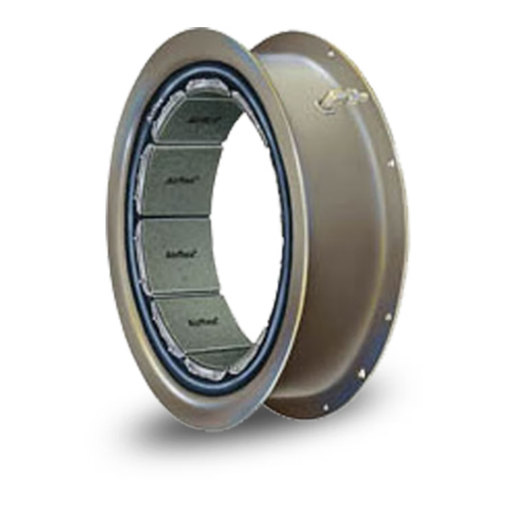
CB Element
Forward this manual to the person responsible
for Installation, Operation and Maintenance of
the product described herein. Without access
to this information, faulty Installation, Operation
or Maintenance may result in personal injury or
equipment damage.
Use Only Genuine Airflex
The Airflex Division of Eaton Corporation recommends the use of
genuine Airflex replacement parts. The use of non-genuine Airflex
replacement parts could result in substandard product performance,
and may void your Eaton warranty. For optimum performance, contact
Airflex:
In the U.S.A. and Canada: 1-800-AIRFLEX (247-3539)
Outside the U.S.A. and Canada: (216) 281-2211
Internet: www.airflex.com
June,1990
(Revised: August, 2005)
203674
©
Copyright Eaton Corp., 2005. All rights reserved.
Warning
Caution:
Replacement Parts
Advertisement
Table of Contents

Related Manuals for Eaton Airflex CB


Summary of Contents for Eaton Airflex CB
- Page 1 Use Only Genuine Airflex Replacement Parts The Airflex Division of Eaton Corporation recommends the use of genuine Airflex replacement parts. The use of non-genuine Airflex replacement parts could result in substandard product performance, and may void your Eaton warranty. For optimum performance, contact Airflex: In the U.S.A.
-
Page 2: Table Of Contents
REPAIR KITS ........20 Friction Shoe, Shoe Pin and Lockwire Kits ..... . . 20 © Copyright Eaton Corp., 1994. All rights reserved. - Page 3 Air Connection Tube Air Connection Gasket Friction Shoe Assembly Air Tube Group (Dual Mounted) Spacer Group (Dual Mounted) Shoe Pin Lockwire 5, 8 Friction Shoe Replacement Kit & 9 DUAL MOUNTED PDF Format © Copyright Eaton Corp., 2001. All rights reserved.
-
Page 4: Introduction
The torque developed is dependent upon rotat- and cord actuating tube which absorbs damag- ing speed and applied air pressure. By limiting ing shock loads. The Airflex CB element as- the applied pressure, the element will act as a sembly requires no lubrication or adjustment. -
Page 5: Installation
Figure 3. will result in permanent damage to the element components. 2.1.3 Figure 4 illustrates a typical CB brake applica- tion. The drum and drum hub are attached to PDF Format © Copyright Eaton Corp., 2001. All rights reserved. - Page 6 The maintenance of the element as- sembly, tolerances and wear limits of friction material, and alignment specifications in this manual apply to all CB applications. Fig. 7 PDF Format © Copyright Eaton Corp., 2001. All rights reserved.
-
Page 7: Mounting Consideration
L 93 (126) 40CB525 45CB525 1-8NC L 163 (221) Dual assemblies use the same values as listed above. For element to element fasteners, use element to spider fastener sizes and torque value. PDF Format © Copyright Eaton Corp., 2001. All rights reserved. -
Page 8: Mounting Spider And Drum Hub
28CB525 7.500 (190.5) 28CB525 14.750(374.7) 30CB525 7.500 (190.5) 30CB525 14.750(347.7) 32CB525 7.500 (190.5) 32CB525 14.750(347.7) 36CB525 7.500 (190.5) 36CB525 14.750(347.7) 40CB525 7.500 (190.5) 40CB525 14.750(347.7) 45CB525 7.500 (190.5) 45CB525 14.750(347.7) PDF Format © Copyright Eaton Corp., 2001. All rights reserved. -
Page 9: Hydraulic Actuation Systems
Note the orientation of the drum flange with ment; however, if one is used, it must be a respect to the air connection(s) on the ele- non-adjustable, mist-type. ment and slide the drum into the element. PDF Format © Copyright Eaton Corp., 2001. All rights reserved. -
Page 10: Operation
The non-asbestos friction material used in Airflex CB units may not de- velop rated torque initially. A short “wear in” period is required. Clutch or brake operation should be moni-... -
Page 11: Maintenance
A tube in this condition also re- removing the element. While squirt- quires replacement of the entire element. inga solvent into an installed clutch PDF Format © Copyright Eaton Corp., 2001. All rights reserved. -
Page 12: Removal Of Element Assembly And Drum (Single And Dual)
Disassemble the long air tube group. When using any solvent, always See Figure 11. follow the appropriate safety 4.3.3 Remove the fasteners attaching the individual precautions. elements together and separate the elements. PDF Format © Copyright Eaton Corp., 2001. All rights reserved. -
Page 13: Removal Of Spider And Drum Hub
Airflex equipment can be obtained by calling or writing: Eaton Corporation Airflex Division 9919 Clinton Road Cleveland, Ohio 44144 Tel.: (216) 281-2211 Toll Free: (800) AIRFLEX or (800) 824-1586 PDF Format © Copyright Eaton Corp., 2001. All rights reserved. - Page 14 PDF Format © Copyright Eaton Corp., 2001. All rights reserved.
-
Page 15: Parts Lists
142096JB —- —- Side Connection 142096JG —- —- 131 X 11 131 x 20 9944 72 x 15 Side Connection and 303370 145096JN —- —- High Coefficient Lining 8 Req’.d PDF Format © Copyright Eaton Corp., 2001. All rights reserved. - Page 16 131 X 11 131 x 20 9944 72 x 15 Side COnnection 142087JG —- —- Side Connection for 142087JZ 131 X 12 —- —- 13 1x 21 201714 —- —- FSPA Mounting PDF Format © Copyright Eaton Corp., 2001. All rights reserved.
- Page 17 Side Connection 142265LB 87 X 12 8518 72 X 11 Side Connection 142265KP Side Connection 142265LD FSPA Mounting Quick Release Valve 142265KN —- —- 145406DF Quick Release Valve 142265KR —- —- PDF Format © Copyright Eaton Corp., 2001. All rights reserved.
- Page 18 87 X 14 8507 72 X 12 Side Connection 142268LB —- —- Side Connection 142268KP —- —- Quick Release Valve 142268KN —- —- 145407DF Quick Release Valve 142268KR —- —- PDF Format © Copyright Eaton Corp., 2005. All rights reserved.
- Page 19 Dual Drilled 87 X 14 8507 72 x 12 Side Connection 142271LB —- —- Side Connection 142271KP Quick Release Valve 142271KN —- —- 145407DF Quick Release Valve 142271KR —- —- PDF Format © Copyright Eaton Corp., 2005. All rights reserved.
- Page 20 —- —- Dual Drilled 27 Req’d. 54 Req’d. 27 Req’d. Side Connection 142081KM —- —- 92 X 8 87 X 16 8501 72 x 13 Side Connection 142081LB —- —- PDF Format © Copyright Eaton Corp., 2005. All rights reserved.
-
Page 21: Dual Element Assemblies
*Notes: The inner element is that which both the short and long air tubes pass through. To find part numbers of components, locate the element number in the parts list for single element application. Find the part numbers in the corresponding item c olumn. PDF Format © Copyright Eaton Corp., 2001. All rights reserved. -
Page 22: Repair Kits
16CB500 146234F 18CB500 146234G 20CB500 146234H 22CB500 146234J 24CB500 146234K 26CB525 146234L 28CB525 146234M 30CB525 146234N 32CB525 146234P 36CB525 146234Q 40CB525 146234R 45CB525 146234S * Extra lockwires supplied with each kit. Copyright Eaton Corp., 2001 All rights reserved. PDF Format... - Page 23 SPECIFICALLY EXCLUDED. period of twelve (12) months from the date of shipment to Purchaser, provided such In no event shall Eaton be liable for special, Product is properly installed, properly main- incidental or consequential damages. Ea- tained, operated under normal conditions and with competent supervision.
Need help?
Do you have a question about the Airflex CB and is the answer not in the manual?
Questions and answers