
Related Manuals for Eaton RPR-2


Summary of Contents for Eaton RPR-2
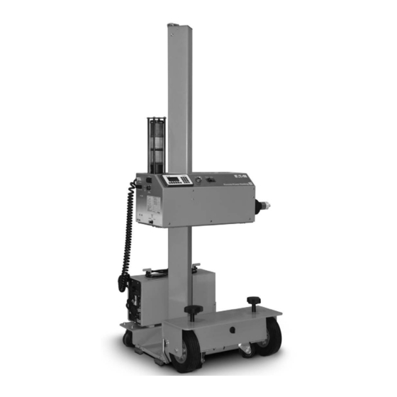
- Page 1 Supercedes October 2013 Instruction Book IB182071EN Effective July 2018 Remote Power Racking System (RPR-2) RPR-2 Low Profile Shown...
- Page 2 SHALL NOT BECOME PART OF OR MODIFY ANY CONTRACT BETWEEN THE PARTIES. In no event will Eaton be responsible to the purchaser or user in contract, in tort (including negligence), strict liability or other-wise for any special, indirect, incidental or consequential damage or loss whatsoever, including but not limited to damage or loss of use of equipment, plant or power system, cost of capital, loss of power, additional expenses in the use of existing power facilities, or claims against the purchaser or user by its customers resulting from the use of the information, recommendations and descriptions contained herein.
-
Page 3: Table Of Contents
D.2 REMOVAL PROCEDURE USING THE RPR-2 SECTION 5: WARRANTY 5.1 GENERAL 5.2 PROCEDURE FOR POWER MODULE REMOVAL 5.3 REMOVING UPS MODULE FROM RPR-2 DEVICE 5.4 REPLACEMENT OF THE UPS MODULE BATTERIES SECTION 6: REPLACEMENT PARTS 6.1 GENERAL 6.2 ORDERING INSTRUCTIONS... -
Page 4: Section 1: Introduction
There is a quick response code (QR Code) on the escutcheon of the current flow is interrupted by the separation of conductors. Thermal head unit and UPS sleeve of the RPR-2. This QR Code is a matrix ionization can generate temperatures as high as 35,000 F . - Page 5 Remote Power Racking System Instruction Book IB182071EN (RPR-2) July 2018 Tablt 1. RPR-2 and RPR-2 Plus DimtnsiNns Overall Stanchion Max. Racking Min. Racking Rotational Height Height Height Height Width Depth Clearance Profile Type RPR-2 Universal Profile 100” 98” 81” 4.875”...
-
Page 6: Section 2: Safe Practices
(RPR-2) July 2018 SECTION 2: SAFE PRACTICES Eaton’s RPR-2 assists in the insertion and removal of power circuit breakers. Although proper use of the RPR-2 reduces the probability of injury by increasing the distance of the qualified operating personnel from the arc flash boundary, must follow local safe... -
Page 7: Section 3: Receiving, Handling, And Storage
If containers must be skidded for any distance, it is preferable to use roller conveyors or individual pipe rollers. When the RPR-2 unit is ready for use, it can be rolled upright with the casters or tilted back and rolled on the larger wheels. - Page 8 Instruction Book IB182071EN Remote Power Racking System (RPR-2) July 2018 Figurt 3.5. PrNfilt Exotrnal Vitw Nf RPR-2 Profile External View of RPR-2 (Univeral Profile Shown) Stanchion UPS Power Cable Counterweight Cable Status Light Tower Jog Button Power Module Cable Control Pendant...
- Page 9 Remote Power Racking System Instruction Book IB182071EN (RPR-2) July 2018 Figurt 3.6. Dtoail Vitw Nf RPR-2 Htad Unio Front External View Transport Latch Insertion Shaft Lock Nameplate Computer Access Port Power Switch Foot Brake Power Cable Pendant Connection Port Rear External View...
-
Page 10: Section 4: Racking Procedures
Using the 1/8” allen wrench, secure the perf-a-torque to the racking shaft. Setscrew Tightness: After the RPR-2 has been used to rack several breakers, check that the perf-a-torque is tight on the racking shaft. Tighten as needed. Fusion Controller Breaker Select Button Figurt 4.4. - Page 11 (Figure 4.3) This will initiate THE RPR-2 WILL THEN INITIALIZE THE REMOVAL PROCESS. ONCE THIS the insertion process on the RPR-2 unit. The amber light on the PROCESS IS COMPLETED THE GREEN AND AMBER LIGHTS ON THE...
-
Page 12: Removing Power Circuit Breakers
Transport Latch. (Figure 3.3) The pendant can be stored IF AT ANY TIME DURING THE REMOVAL PROCESS AN OVER-TORQUE by wrapping the cord around the post at the base of the RPR-2 OCCURS THE AMBER LIGHT ON THE PENDANT AND TOWER WILL unit. -
Page 13: Section 5: Warranty
5.2 PROCEDURE FOR POWER MODULE REMOVAL Note: This prNctdurt rtquirts assisoanct. Lay the RPR-2 over on a brace approximately half way up the stanchion. Make sure the Power Module is located closest to the top end of the stanchion for removal. -
Page 14: Removing Ups Module From Rpr-2 Device
5.4 REPLACEMENT OF THE UPS MODULE BATTERIES In certain cases where the UPS needs to be replaced due to a Once the UPS module has been removed from the RPR-2 device, warranty repair, the UPS will need to be removed. -
Page 15: Replacement Of The Ups Module Batteries
RPR-2 UPS revision. Follow the steps listed in section 5.3 to remove the UPS module from the sleeve. Remove the ¼-20 nuts (x4) that hold the sleeve to the RPR-2 base (Figure 5.13) Note:... -
Page 16: Section 6: Replacement Parts
Describe the item, give the style number, and specify the quantity required. Specify the method of shipping desired. Send all orders or correspondence to the nearest Eaton’s Electrical Services & Systems sales office or contact the PBC at (877) 276-9379 for assistance. -
Page 17: Appendix A: Ite-Hk Air Circuit Breaker
(Figure 4.3) This will initiate alignment (amber pendant and tower light will illuminate). the insertion process on the RPR-2 unit. The amber light on the Horizontal alignment can be achieved with the casters and pendant and on the tower light will illuminate while the power vertical alignment by raising or lowering the Power Module. -
Page 18: Removal Procedure Using The Rpr-2
Transport Latch. (Figure 3.3) The pendant can be stored predetermined through Arc Flash calculations.) by wrapping the cord around the post at the base of the RPR-2 unit. (Figure 3.5) Place the RPR-2 unit cover over the base while in storage. (Figure 3.4) -
Page 19: Appendix B: Ge Am-5 Circuit Breaker
(Figure 4.3) This will initiate Select the INSERT direction with the Insert/Remove switch. the insertion process on the RPR-2 unit. The amber light on the (Figure 4.1) pendant and on the tower light will illuminate while the power Select the correct racking adaptor for the breaker being circuit breaker is in the insertion process. -
Page 20: Removal Procedure Using The Rpr-2
Transport Latch. (Figure 3.3) The pendant can be stored Take the Pendant and move a safe distance away from by wrapping the cord around the post at the base of the RPR-2 front of the power circuit breaker. (The distance should be unit. -
Page 21: Appendix C: Ge Magneblast Vertical Lift
2) The switchgear must be in good condition and setup per the original switchgear IB. 3) Move the RPR-2 unit in front of the switchgear cell. 4) If engaged, release the Transport Latch to allow for vertical movement of the Power Module. (Figure 3.3) - Page 22 (Figure C.9) 18) Attach the vertical control box to a convenient location in 20) Position the RPR-2 in front of the cell, near the racking adapter Figurt C.5. Insoalling Racking Adapotr HNusing Figurt C.8. Insoalling Racking Adapotr HNusing Figurt C.6.
-
Page 23: Removal Procedure Using The Rpr-2
If the breaker was inserted, the green light will be off and no insertion racking will be allowed. 25) Engage the foot brake on the RPR-2 truck by stepping down on the lever. (Figure 4.6) Verify that the correct power circuit breaker program and the insert direction are selected by viewing the LCD screen on the Fusion Controller. -
Page 24: Appendix D: Westinghouse Dh Air Circuit Breakers
(Figure 4.3) This will initiate Select the correct breaker program on the Power Module by the insertion process on the RPR-2 unit. The amber light on the pressing and releasing the Breaker Select Button until the pendant and on the tower light will illuminate while the power desired program is displayed on the Fusion Controller. -
Page 25: Removal Procedure Using The Rpr-2
Lower the Power module to the lowest position and engage the Transport Latch. (Figure 3.3) The pendant can be stored by wrapping the cord around the post at the base of the RPR-2 m WARNING unit. (Figure 3.5) Place the RPR-2 unit cover over the base IF AT ANY TIME DURING THE REMOVAL PROCESS AN OVER-TORQUE while in storage. - Page 26 EaoNn 1000 Eaton Boulevard Cleveland, OH 44122 United States Eaton.com © 2018 Eaton All Rights Reserved Eaton is a registered trademark. Printed in USA Publication No. IB182071EN All trademarks are property July 2018 of their respective owners.
Need help?
Do you have a question about the RPR-2 and is the answer not in the manual?
Questions and answers