
Related Manuals for Pfannenberg DTI 8665


Summary of Contents for Pfannenberg DTI 8665
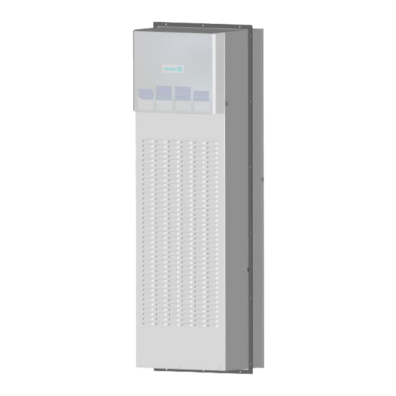
- Page 1 嵌入式机柜空调操作及使用说明书 DTI 8665 50/60Hz 系列 Operating and assembly instruction For side-mounted cooling units DTI 8665 50/60Hz...
-
Page 2: Table Of Contents
1 手册提示 ................................8 2 搬运 ..................................8 2.1 运输 ................................. 8 2.2 储运 ................................. 8 2.3 开箱 ................................. 8 3 供货范围 ................................9 4 一般信息 ................................9 5 铭牌 ..................................9 6 安全 ..................................10 7 功能 ..................................10 7.1 配置与功能... - Page 3 11.1 概述 ................................18 11.2 操作显示器 ..............................18 11.3 启动/自检模式 ............................18 11.4 门触点 ................................. 19 11.5 人体感知降噪模式 ............................. 19 11.6 设备故障 ..............................19 12 参数查看与设置 ..............................20 13 清洁和维护 ................................ 22 13.1 清洁 ................................22 13.2 维护 ................................22 14 停止使用...
- Page 4 7.1 Function and configuration ........................29 7.2 Operating principles ............................ 30 7.3 Condensate..............................30 8 Technical data ................................ 31 8.1 Circuit Diagram ............................31 8.2 Spare parts ..............................32 8.3 Installation Cut-out ............................32 8.4 Installation for sealing..........................33 8.5 Airflow principle ............................33 8.6 Technical Data .............................
- Page 5 15 Trouble shooting ..............................44 16 Warranty Conditions ............................44 AppendixⅠ................................45 Appendix Ⅱ................................46 Appendix Ⅲ................................47...
-
Page 6: 手册提示
请在安装机组前完整仔细阅读此手册。 本手册构成标准产品不可分割的一部 分,必须保存至机组报废为止 1 手册提示 此手册为百能堡电气科技有限公司(以下简称百能堡)提供的门装或侧装螺栓固定,嵌入式机柜空调系列的安 装运行指南。 本手册中,安全提示和其他信息以下形式出现: 如果没有严格遵守所述的措施,将有生命危险或造成健康危害。 如果没有严格遵守所述的措施,将可能因电击造成生命或健康危害。 如果没有严格遵守所述的措施,将有可能造成生命财物损失。 提示包含关于所述措施或指导的额外信息。 2 搬运 2.1 运输 • 运输时保持机柜空调处于最终使用时相同的摆放状态。 • 如果整体机柜需要运输,请在运输前将机柜空调拆下并单独包装。 2.2 储运 • 储存环境不应超过+70℃。 • 储存时使机组处于最终使用时的摆放状态。 不按照这些指导操作,将导致保障条款失效。 2.3 开箱 开箱过程中应当仔细查看机柜空调,看是否存在因运输造成的破坏,尤其注意是否有部件松动、凹坑、擦伤和 漏油等。任何损坏应当立即通知承运商(见章节16保障条款),并且适用“百能堡产品售后服务声明“的最新版 本。 • 在处理包装材料前,务必确认里面没有任何附加部件。 685408025B... -
Page 7: 供货范围
机组的钣金件边缘有可能残留金属毛刺,在维护或安装时务必带保护手套。 要求保障时,需要提供故障的确切信息(如有可能请提供照片),机种型号和序列号。 3 供货范围 供货范围包括: • 机柜空调 • 附件包(包括紧固件,插头式电气连接器等) • 特殊的附件(如适用) 4 一般信息 • 百能堡可以妥善处理旧设备,但客户需承担运输费用. • 百能堡生产的机柜空调不含以下物质: - 硅合成物 - 多氯联苯 - 多氯三联苯 - 石棉 - 甲醛 - 镉 - 液态有害物质 • 对每台机柜空调进行检查以确保它是完全依照9.ProdSV的规定(德国事故预防法规)。 • 交货前百能堡已对每台空调在工厂进行电气安全检测。 5 铭牌 安装和维护,请注意机器背部铭牌标注的详细技术信息。 685408025B... -
Page 8: 配置与功能
6 安全 • 由百能堡生产的机柜空调是专为机柜散热(IP55)而设计的。 • 该设备只适合在固定地点平稳运行。 • 任何其他使用范围被视为非授权使用, 并将不作保修承诺。电气设备应定期检查。任何异常如连接松脱或烧 焦的电缆必须被立即修复。 • 只有专业技术人员才能对热交换系统和电气部件进行操作。 • 请务必遵守相应的安全和环保法规。 任何清洁或维护操作之前,需切断机柜空调电源。 只有原厂备件可以使用。 7 功能 7.1 配置与功能 1. 压缩机保护装置 2. 智能控制系统 3. RS485通讯功能 4. 湿度传感器 5. 机柜内部加热器-2000W (可选) 6. 冷凝水蒸发器 (可选) 7. 人体感知降噪功能(可选) 8. -40℃ +55℃外部环境温度 9. 内部控制温度 +25℃ +45℃... -
Page 9: 冷凝物
7.3 冷凝物 •在蒸发器上发生的冷却过程中,空气中的水分被凝聚成冷凝水。为了避免对电控柜及本制冷系统发生任 何损害,必须排出冷凝水。 冷凝水排放方式如下: • 带冷凝水蒸发器(可选)的制冷设备在正常情况下,可以蒸发掉水分。但为防止蒸发器故障后产生的冷 凝水溢流,请连接冷凝水管路,然后再通过水管排出。始终确保冷凝水正确地排出。在特定情况下有可能会 发生凝结水过量,例如,机柜不密封或机柜内部温度经常低于露点温度。 在正常运行过程中发生冷凝水过量,请检查机柜的密封。 我们建议安装一个门接触开关, 当机柜门被打开时机柜空调将自动关闭以防止过度冷凝水。 8 技术规格书 8.1 电气原理图 Int Fan 11-- C 12 dc IOut1 I T FA IOut C 12 Main C E T FA S485 12 dc C 11 11-- O Temp4 E t Fan H eater... -
Page 10: 备品备件(请使用百能堡物料号来采购备用件
8.2 备品备件 (请使用百能堡物料号来采购备用件) 备用件 DTI 8665 内风机 18861100031 外风机 18861100032 人体感知装置 18865500055 压缩机 18861200010 外风机电容 18864000000 内风机电容 18864000007 压缩机电容 18864000014 过滤干燥器 18865000000 控制器 物料号位于控制器上 8.3 安装开孔 685408025B... -
Page 11: 安装密封泡棉
8.4 安装密封泡棉 机柜安装板 密封泡棉 机柜空调 8.5 气流原理 685408025B... -
Page 12: 技术参数
A35/A35: 2100 / 2360 W (无可选项) 可选: 冷凝水蒸发器 30-110W (A35/A35 ca. 70W) 型号 DTI 8665 IC LAP DTI 8665 IC LAP RS DTI 8665 IC CM LAP DTI 8665 IC CM LAP RS 电流 * 20 A 20 A 20 A... -
Page 13: 安装工作
9 安装 9.1 概述 • 正确选择机柜空调在机柜上的安装位置,保证良好的通风。 • 机柜空调之间或是机柜空调和墙壁的距离必须保证至少500毫米。 • 在机柜内部,空调的电器连接端子处需预留至少60mm空间。 • 在机柜内部,电气元件不得阻碍空气循环。 • 机柜空调在安装时,机柜空调的电源必须断开。 • 安装现场必须受到保护,免遭污染。 如果机柜空调是装在机柜门上,必须检查门的铰链能够支持机柜空调的重量或当门被打开机柜时,不会翻倒。 金属碎屑可能损坏机柜。如果在安装现场开安装孔,确保使用保护罩,以免切屑进入机柜,损坏电气元件。 9.2 安装工作 机柜安装面要开好空气通风口和螺栓安装固定孔,尺寸根据开孔尺寸。 如机柜未预留机柜空调的开口,在机柜上切出开口(见章节8.3 ),然后去除剪边毛刺。 2) 在机柜内侧,取出附件包内的螺栓、平垫片、弹垫、螺母及螺栓(标号3,4,5,6,7)将空调锁紧。 3) 将电线按照接线图(见机柜空调背部)连接到连接头(附件包中),并连接到机柜空调。 - 导线尺寸:1.0 – 2.5平方毫米或AWG18 - AWG14 (在电缆的大小选择,应参照相关法规要求!) 将机柜空调插上电源(见章节9.3) 1. 机柜空调组 2. 机柜侧板或机柜门 3. 牙棒 4. -
Page 14: 电气连接
空调底部的冷凝水排水口及排沙口需伸出安装的机柜外部,安装后不可对冷凝水排水口及排沙口进行遮挡, 以防冷凝水排水及排沙功能失效。 9.3 电气连接 • 机柜空调应当经由断路器连接到电源(请选择合适的断路器),断开断路装置时,其触点间隙应不少于3毫米。 • 电源线上不可以串接温度传感器。 • 电源线上需要串接铭牌注明的保险丝,作为线路保护。 • 电源连接和维修,如果适用,只能由授权的经过培训的电工来进行。 机柜空调电气连接端口: 电气 序号 符号 定义 导线尺寸 端口 交流电源火线 交流电源零线 交流电源地线 Max 2.5mm²/ AWG14 悬空 门触点 电源故障信号 Max 1.0mm²/ AWG18 3/4/5/6 悬空 设备故障信号 Lout 1+ 20mA 湿度输出正极 Lout 1- 20mA 湿度输出负极... -
Page 15: 运行条件
电源电压和频率必须符合铭牌标示值,请认真查看机器上的电气标签。如果电压过高可能会导致器件损坏。 电源线及告警线须客户自备。 故障指示连接最大容量为: 230V,1A 通讯连接: 机柜空调支持标准的Modbus规约RTU模式,共有五种波特率可选,出厂默认设置为9.6Kbps。 RS-485从设备端口最多允许32台设备利用双绞线通讯电缆通过菊型连接方式组成通讯网络。 为了将多台空调连接成菊型网络形式,应采用以下方法: • 将屏蔽线在主机端一点接地即可,最后一台机柜空调需匹配接120欧姆的电阻。 • 为了避免任何破坏性的影响,建议使用一根带有护线套的双绞电缆线。 • 在安装过程中必须确保它们不会被附近的潜在干扰源影响(如电源线,具有相对较高的电磁辐射的器件) 将每台空调的+、- 端子一一对应的连接起来,如下图所示: 双 绞 线 屏 蔽 终 端 匹 配 电 阻 网 络 链 接 示 意 图 请按照线路图接线,错误的接线将导致设备无法正常工作甚至损坏! 无需另接外部电源! 10 运行条件 • 电源电压范围230Vac± 10%以内。 •... -
Page 16: 投入使用和功能
11 投入使用和功能 • 机柜空调包含的功能及可选项(见章节 7.1). 11.1 概述 • 机柜空调配有温度控制系统,机柜内部温度通过温度传感器来测量。通过操作显示器可以设定不同的机柜内温 度(见附表Ӏ)。 • 机柜空调具有上电检测、运行时实时监测功能。上电检测过程中如果有故障,空调会发出相应的报警,这使 得在进入工作模式之前更方便的排查设备故障。 机柜空调只能在装有前盖的情况下运行,否 会因散热不良造成机柜空调被损坏。 11.2 操作显示器 机柜空调装有操作显示器,上电后操作显示器显示机柜实时温度;如有机柜空调发生故障或报警输出时 操 作显示器显示报警代码同时操作显示器上的警报灯点亮并伴随报警声。机柜空调故障排除代码(见章节15)。 11.3 启动/自检模式 机柜空调通电前,若连接机柜空调的门触点为断开状态, 机柜空调不能启动,直至机柜空调的门触点为闭 合状态机柜空调才能启动。机柜空调进入启动模式持续30秒之后进入自检模式持续约120秒。自检模式不受外部 环境影响,自检模式过程中若有设备故障 继续运行,直到自检模式运行结束并显示相应故障报警代码。须排 除机柜空调对应的故障后机柜空调才能进入正常工作模式,若自检过程无故障 自检结束后直接进入正常工作 模式。 模式 时间曲线 特征 启动模式 显示机柜当前“实时温度” t=0s 内风机运行 t=30s 外风机运行 t=40s 内风机停止... -
Page 17: 门触点
11.4 门触点 确保安全门限位开关应连接到指定端口(见机壳上线路图或章节8.1电气原理图)当打开机柜门时门触开关即 被断开,机柜空调所有马达延时依次关闭之后产生报警。 为了避免任何破坏性的影响,建议使用一根带护线套的双绞线电缆。 无需另接外部电源。 如果门触点开关未被使用,需将其短接(位置见机壳标签或章节8.1电气原理图) 11.5 人体感知降噪模式 当机柜空调的人体感知装置感应到有人体移动(1.0~1.5m/s)速度接近机柜空调时,机柜空调会自动降低内风 机转速进入降噪模式,若人体感知装置动作时间内探测到有人体连续移动信号时其将会重新计时直至未探测到可 移动的信号才会退出降噪模式。 机柜空调降噪模式会影响机柜空调制冷效果 •人体感知装置正前方 1.5m 范围内不可有屏蔽及遮挡物,否 会影响人体感知模块工作从而导致降噪模式不能 正常工作。 •人体感应区域 5m 范围内,感应角度:170*360 度(前半球)不可有不停运动及动荡不定的移动物体,否 人 体感知模块会一直开启降噪模式从而影响机柜空调的制冷效果。 11.6 设备故障 •机柜空调电源故障报警触点X54—1,2脚为常闭触点,上电后无电源故障为闭合,有电源故障时将引起触点 断开并显示告警代码(见章节15)。 •机柜空调设备故障报警触点X51—1,2脚为常闭触点 上电自检结束后无设备故障为闭合,有设备故障时将引 起触点断开并显示告警代码(见章节15)。 故障信号线安装不受到任何特殊要求限制 685408025B... -
Page 18: 参数查看与设置
12 参数查看与设置 • 机柜空调可以通过操作显示器 对参数进行监控及设置。 或上位机 • 机柜空调电子控制系统包括主控制系统、操作显示系统。面板上的指示灯从左到右排列的功能含义如下表: 指示灯 指示灯含义 长亮 备注 上电自检 自检 启用 制冷 正在制冷 启用 制热 正在制热 启用 ---- 除湿 无 操作面板 外风机 风机运转 启用 告警 告警发生 启用 12.1. 参数查看操作 操作面板主界面下长按“Select”键,当操作显示器显示 SEE,再按“Select”键,然后通过面板上的 “▼”或 “▲”键选择参数“Pb1”、“t1”、“rh”、“U”、“SC”、“add”、“bau”、“r1”、“r2”、“no6”、 “no7”,在任意一个选中的参数代码界面下按“Select”键,进入其相应参数的参数值,按“Mode”键返回上 层菜单。在任意操作界面的菜单下连续按 Mode”键或静置 5min 无任何操作, 操作面板会自动返回到主显示 I)。... - Page 19 ·在任意操作界面的菜单下连续按 Mode”键或静置 5min 无任何操作, 操作面板会自动返回到主显示界面。 操作示例:“t1” 设置修改 操作面板主界面 按操作面板 操作面板主界面 显示“PASS” 显示“SEE” 按操作面板“▼”键 “Select”键 长按“Select”键 使用“▲”或“▼” 按操作面板 按“▲”或“▼”键 键选择 “Select”键 输入密码 “666” 按操作面板 按操作面板 使用“▲”或“▼” “ ” “tp” “Select”键 “Select”键 键选择 使用“▲”或“▼” 默认值: 长按“Mode” 按操作面板 键修改数值 “35℃” “Select”键保存 键返回主界面 ·示例中在任意操作过程若需取消操作或返回上层级菜单只需按“Mode”键即可,长按 Mode”键或静置 5 分 钟无任何操作,...
-
Page 20: 清洁和维护
12.4. 远程设置 机柜空调支持标准的 Modbus 规约 RTU 模式,参数的设置也可以通过上位机软件远程访问或设置。 II) (通讯地址参数见附表 13 清洁和维护 在任何清洁或维护操作前,请切断空调电源。 13.1 清洁 建议每个月对机柜空调进行维护,例如对冷凝回路进行清洗,将提高设备的运转效率以及可靠性。具体维护 周期视使用环境而定。 特别注意以下说明: • 清洗外部风道,冷凝器以及外风机。 • 用软刷或压缩空气进行作业。(注意不要伤到翅片) 步骤如下: 1)断开机柜空调电源。 2)打开外壳。 3)清洁风道。 4)清洁外风机。 5)清洁交换器。 6)装回外壳 7)接通电源并观察上电自检,确保设备运转正常。 防止电气元件漏电。不要使用任何尖锐或锋利的物体。 防止热交换器损坏。 防止外罩电气连接损坏。在拆卸外罩时,应当手动拔去外罩里面的电气连接。安装时,不要忘插上该电气连接! 13.2 维护 15。 设备出现故障后,会自动提示故障代码,主要故障代码对应的故障原因见章节 在每一次维护后,请等待设备上电自检结束后查看自检情况,以确保设备能够正常运转。 14 停止使用 如果机柜空调在较长时间内未被使用,请切断电源。确保未经授权的人员不会擅自启动空调。 机柜空调需要报废处理时,需根据相关环保法规由专业人员进行处理。(见章节... -
Page 21: 保障条款
非授权人员不可检修此设备 报警代码列表: 报警代码 描述 故障排除方法 AL01 传感器 1 错误 检查感温头 Pb1 AL02 传感器 2 错误 检查感温头 Pb2 AL03 传感器 3 错误 检查感温头 Pb3 AL04 传感器 4 错误 检查感温头 Pb4 AL05 机柜门打开 检查门开关 AL06 内风机故障 检查内风机 AL07 系统压力过高 检查外部风机与冷凝器 AL08 压缩机故障 检查压缩机... -
Page 22: 附表 I
附表 I 显示器参数: 一级菜单 二级菜单 描述 最小值 最大值 默认值 单位 参数 参数 空调内循入风口温度(只读) ℃ 空调内循出风口温度(只读) ℃ 空调外循环入风口温度(只读) ℃ 空调外循环出风口温度(只读) ℃ 温度 机柜内部温度设定 ℃ (-tp-) t2 ° ) 节能温度设定 ℃ t5 ° ) 加热器开启温度设定 ℃ t6 ° ) 加热器关闭辅助温度设定 ℃ t8 ° ) 空调内循环出风口温度设定... -
Page 23: 附表 Ii
附表 II 通讯地址: 地址 R/W 说明 值属性 数据说明 0x12 Boolean AL01 0x13 Boolean AL02 0x14 Boolean AL03 0x15 Boolean AL04 0x16 Boolean AL05 0x17 Boolean AL06 0x18 Boolean AL07 0x19 Boolean AL08 0x20 Boolean AL09 0x21 Boolean AL10 0x22 Boolean AL11 0x23 Boolean... -
Page 24: 附表 Iii
附表 III 波特率: 通讯协议 Modbus Rtu Slave Code 1200 2400 4800 波特率 9600 19200 38400 所有附表参数请误擅自更改, 不按照百能堡的指导操作将导致产品保障条款失效。 所有未提及参数为百能堡预留, 最终使用及解释权归百能堡所有。 685408025B... -
Page 25: Hints On The Manual
1 Hints on the manual This handbook contains instructions for the installation and operation of door or side-mounted, bolt-on Cooling Units provided by Pfannenberg. In this manual, safety recommendations and other information are structured as follows. If the measures described in the following are not strictly observed there is danger to life and health. -
Page 26: Unpacking
(Also refer to warranty 16 Any damage must be reported immediately to the forwarding agent Moreover, the latest edition of the "Pfannenberg After Sales Service Declaration" shall apply. •Before disposing of packing material ensure that it does not contain any loose components. -
Page 27: Safety
6 Safety Cooling units produced by Pfannenberg are designed for use in dissipating heat from switch cabinets (IP 55). The cooling unit is only suitable for installing on the stationary operation. Only the authorized specialist can work on the cooling system and electrical components. -
Page 28: Operating Principles
11. Start-up self-check and real-time self-check 12. IP55 protection class See section 8 Please refer to technical data for the detailed function of the cooling unit. 7.2 Operating principles The compressor 1 compresses the refrigerant until high pressure is achieved. During this process temperature increases. -
Page 29: Technical Data
operation. In order to prevent the excessive condensate we recommend to install a door contact switch. It will switch off the cooling unit when the switch cabinet door is open. 8 Technical data 8.1 Circuit Diagram Int Fan 11-- C 12 dc IOut1 I T FA... -
Page 30: Spare Parts
8.2 Spare parts Please order your spare parts only with the Pfannenberg-parts-number. Spare parts DTI 8665 Internal fan 18861100031 External fan 18861100032 Body Posture Sensor 18865500055 Compressor 18861200010 External fan capacitor 18864000000 Internal fan capacitor 18864000007 Compressor capacitor 18864000014 Filter dryer... -
Page 31: Installation For Sealing
8.4 Installation for sealing Panel of cabinet Sealing Cooling unit 8.5 Airflow principle Read this manual completely and carefully before installing the unit. 685408025B... -
Page 32: Technical Data
A35/A35: 2100 / 2360 W (w/o options) Power consumption Condensate evaporator CM 30-110W (A35/A35 ca. 70W) Type DTI 8665 IC LAP DTI 8665 IC LAP RS DTI 8665 IC CM LAP DTI 8665 IC CM LAP RS 20 A 20 A 20 A 20 A... -
Page 33: Installations
* ID late Information ° Free blowing-in °° eed additional electrical terminal space 6 mm, total 12 mm. 9 Installations 9.1 General •For effective cooling & ventilation, correct installation & ventilation of the cooling unit is very important. •The distance must be kept at least 500mm between units or the unit to the wall. •The cooling unit’s electrical connection terminal requires at least 60mm space and the electrical components shall not impede air circulation in the internal cabinet. -
Page 34: Electrical Connection
1. Cooling unit 2. Switch cabinet wall or door 3. Thread rod 4. Flat washer 5. Springs washer 6. Nuts 7. Bolts Vents for rain water and dust on the bottom of the cooling unit must not be blocked or sealed inside the cabinet, otherwise the water and dust drainage function would fail. - Page 35 Electrical connection port of cooling unit: ort name Serial number Symbol Definition Cable size Mains “L” Mains “N” Mains “PE” Max 2.5mm²/ AWG14 Free Door contact Power fault signal Max 1.0mm²/ AWG18 3/4/5/6 Free Device fault signal Lout 1+ 20mA Humidity current output“+” Lout 1- 20mA Humidity current output“-”...
-
Page 36: Operating Condition
lease follow the wiring diagram it will damage the equipment with wrong wiring. o e ternal voltage may be applied! 10 Operating condition •The voltage must be within 23 ± 1 % of the value indicated. •The frequency must be within ±3Hz of the value indicated. •Ambient temperature must be below 55℃. -
Page 37: Operation Display
11.2 Operation display The cooling unit is provided with an operation display,after the power supply is switched on, then cabinet internal temperature is shown,This indicates the unit works properly. If there is a failure or an alarm, the alarm lamp will be turned on and accompanied by an alarm sound, which makes it easier to diagnose the cooling unit. -
Page 38: Human Perception Low Noise Mode
11.5 Human perception low noise mode When the human body sensing device senses movement of speed between 1. ~ 1.5 m/s near the cooling unit internal fan goes into low noise mode. ow noise mode runs with time relay to avoid frequent on and off. Unit e its from low noise mode when no further movement is detected. -
Page 39: Parameters View And Settings
12 Parameters View and Settings •Parameters of cooling unit can be monitored and set via operation display. •Cooling unit control system includes control board operation display. Sign Description ighting emark Self-check Self-check Available Cooling Cooling Available Heat unning Available Humidity ----- ot used Operation Display... - Page 40 Operation sample: Change “t1” Setting Operation Panel Operation panel “PASS” “Select” Key Press “▼”Key “SEE” Press Continuous press “Select” “▲”or“▼”key Press “▲”or“▼” Press “Select” Key Press select input “666” “Select” “Select” Press Press “▲”or“▼” “tp” Press “ ” key select Continuous press “Select”...
-
Page 41: Cleaning And Maintenance
13 Cleaning and Maintenance lease cut off the cooling unit’s power before carrying out any cleaning or maintenance operation. 13.1 Cleaning The operation efficiency and reliability of the equipment will be improved by periodic cleaning and maitenance call our service team for further service cooperation. ay special attention to the following instructions: •Use a soft brush or compressed air Medium pressure to avoid damage to the fins . -
Page 42: Trouble Shooting
15 Trouble shooting In spite of careful maintenance the equipment may still have a failure sometime. The real-time self-check function help diagnose the failure. If a fault occurs the display will show the relevant alarm code elow is the trouble shooting guide . Alarm codes list: Alarm code Description... -
Page 43: Appendixⅰ
AppendixⅠ Shown parameters (operation display): Hierarchy 一 Hierarchy 二 Description Min. Ma . Default Unit arameter arameter Cabinet air inlet tempeture (Read only) ℃ ℃ Cabinet air outlet tempeture(Read only) ℃ Ambient air inlet tempeture(Read only) Ambient air outlet (Read only) ℃... -
Page 44: Appendix Ⅱ
may lead to malfunction of the unit. The high temperature alarm point is 15 ℃ higher than “t1”. The high temperature alam goes off when internal temperature is 5 ℃ under alarm point. Appendix Ⅱ Postal address: Addres Attribute Explain 0x12 Boolean AL01... -
Page 45: Appendix Ⅲ
Appendix Ⅲ Baud rate: Communication protocol Modbus Rtu Slave Code 1200 2400 Baud rate 4800 9600 19200 38400 Random change to parameters may lead to malfunction of the unit and hence render the warranty null and void. www.pfannenberg.com/disposal 685408025B... - Page 46 百能堡电气科技(苏州)有限公司 中国苏州工业园区杏林街 108 号 邮编:215026 电话:+86-512-6287-1078 传真:+86-512-6287-1077 邮箱:service@pfannenberg.cn http://www.Pfannenbergchina.com Pfannenberg Electro-Technology (Suzhou) Co.,Ltd. No. 108 Xinglin street, SIP, Suzhou 215026, Jiangsu, P.R.C Tel: +86-512-6287-1078 Fax: +86-512-6287-1077 e-mail: service@pfannenberg.cn http: //www.pfannenberg.cn 685408017 /11-2017...
Need help?
Do you have a question about the DTI 8665 and is the answer not in the manual?
Questions and answers