Pfannenberg DTT Series Operating Manual
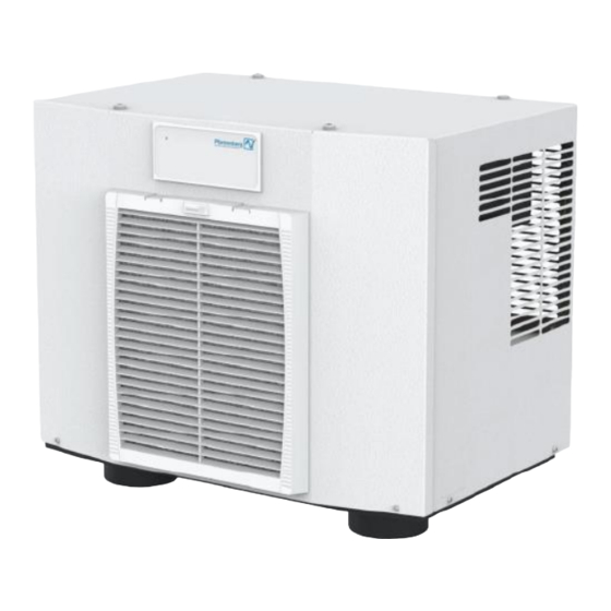
Roof-mounted cooling unit multi controller (mc) – 230 v
Hide thumbs
Also See for DTT Series:
- Original operating manual (271 pages) ,
- Operating manual (309 pages)

Related Manuals for Pfannenberg DTT Series


Summary of Contents for Pfannenberg DTT Series
- Page 1 Operating Manual Roof-mounted Cooling Unit DTT series 6101 / 6201 Multi Controller (MC) – 230 V Original instruction manual – Version 1.4, July 2022...
-
Page 2: Table Of Contents
About this manual ................................5 Use and safekeeping ..............................5 Exclusion of liability ................................ 5 Explanation of the notes ..............................6 Marking of contents ................................ 7 1.4.1 Handling instructions ..............................7 1.4.2 Links and cross references ............................7 Safety ....................................8 Intended use .................................. - Page 3 Assembly and initial commissioning ..........................29 Safety information ................................ 29 Transport ..................................30 4.2.1 Transporting the cooling unit ..........................30 4.2.2 Crane transport ..............................31 Storage ..................................32 Unpacking ..................................32 Assembly ..................................33 4.5.1 General .................................. 33 4.5.2 Making the assembly cut-out for the DTT-cooling unit ................... 33 4.5.3 Sticking on the surface seal ...........................
- Page 4 Rectification of operating faults ............................. 67 General ..................................67 7.1.1 Error messages ..............................68 7.1.2 System messages ..............................71 Decommissioning ................................72 Temporary decommissioning ............................72 Final decommissioning ..............................72 Dismantling and disposal ............................... 73 Safety information ................................ 73 Dismantling .................................. 74 Disposal ..................................
-
Page 5: About This Manual
Pfannenberg reserves the right to change this document, including the exclusion of liability, at any time without notice and is not liable for any consequences of this change. -
Page 6: Explanation Of The Notes
Explanation of the notes The warnings are indicated by signal words which express the degree of danger. The warnings must be heeded to avoid accidents, injuries and property damages. Explanation of the warnings in this manual: DANGER Brief description of the danger The signal word DANGER indicates an imminent danger. -
Page 7: Marking Of Contents
Marking of contents 1.4.1 Handling instructions Handling instructions are indicated in this manual as follows: Requirements Requirements and additional warnings Required tools and materials Tools and materials required for handling Procedure <Handling steps> … – <Intermediate result / Further instructions> …... -
Page 8: Safety
Safety Intended use The Pfannenberg roof-mounted cooling units of the DTT-series are stationary cooling units for heat dissipation from switch cabinets. The DTT-cooling units are mounted on the switch cabinet roof. The cooling units have different cooling capacities. See the chapter "Refrigeration circuit", Page 27for exact capacity data. -
Page 9: Foreseeable Misuse
Foreseeable misuse The following points describe a foreseeable misuse of the unit: • Use of the unit as a storage place, work platform. • Attachment of transport aids. • Installation in unsuitable locations. • Outdoor operation. • Operation outside of the permissible technical data. See section "Technical data". •... -
Page 10: Terms Of Warranty
The following must be observed to assert warranty claims and to return the unit: • Attach a precise description of the defect and the SRO (RMA) number assigned by Pfannenberg to the cooling unit. • Enclose proof of purchase (copy of delivery note or invoice). -
Page 11: Unit Description
Only use cooling units in stationary operation. The Pfannenberg roof-mounted cooling units of the DTT-series are designed for heat dissipation from switch cabinets. The innovative arrangement of the climate circuits prevents a cold bridge to the switch cabinet,; the risk of condensate forming in the switch cabinet is avoided. -
Page 12: Functional Description
Functional description 3.4.1 Air circuit CAUTION Risk of burns Risk of burns due to high temperatures at the ambient air outlet. The air outlet can get very hot depending on the ambient temperature. • Do not hold any parts of the body directly in front of the ambient air outlet (A). G00027 Front view View from below... -
Page 13: Filter Adapter (Option)
3.4.2 Filter adapter (option) G00051 Fig. 2: Filter adapter on the cooling unit For permanent protection of the external air circuit from contamination, the optional filter adapter (1) can be fitted with a filter mat (2) at the air inlet (3) of the cooling unit. The filter adapter (1) is simply clipped into the air inlet (3). -
Page 14: Quick-Change Frame (Option)
3.4.3 Quick-change frame (option) G00028 Fig. 3: Quick-change frame DTT-cooling units (1) with quick-change frames (2) are quick and easy to assemble. The flexibility allows easy, convenient replacement of the cooling units. NOTE Quick-change frames that are assembled with a “Performance-Cut” offer optimum colling unit performance at minimum current consumption, see chapter "Dimensions of "Performance-Cut”... -
Page 15: Flat Duct System (Option)
3.4.4 Flat duct system (option) WARNING Danger of fire due to short-circuits Formation of condensate in the switch cabinet can lead to a fire risk due to short-circuits. Condensate can form on the flat duct system. • Check the flat duct system in the switch cabinet regularly for condensate formation. •... - Page 16 3.4.4.1 PAD-frame Three different PAD-frames are provided for the flat duct system (see Fig. 5): • DTT-cooling units 6101/6201 size 1 (500 W/1000 W): PAD-single-duct system with PAD-single-duct frame. • DTT-cooling units 6301/6401 size 2 (1500 W/4000 W): PAD-dual-duct system with PAD-dual-duct frame. •...
-
Page 17: Controller
3.4.5 Controller The controllers are control units for setting refrigeration functions and operating data. They allow readouts of system messages and diagnostic data. The controllers have a service interface at which different configurations are possible. They also have a connection for collective fault signals. G00018 Fig. - Page 18 Cooling units with a Multi-Controller (MC) have a control unit with a green LED light and a control panel. The control unit is on the unit cover. Steady lighting of the green LED light when mains voltage is applied indicates fault-free operating mode. System information is displayed on the control panel.
-
Page 19: Refrigeration Circuit
3.4.6 Refrigeration circuit G00004 Fig. 7: Refrigeration circuit Compressor Condenser (external) Condenser Evaporator fan (internal) Expansion valve Electronic control with temperature sensor Evaporator The cooling units consist of different components, see Fig. 7. • The compressor (1) compresses the refrigerant with high pressure. The temperature rises. •... -
Page 20: Safety Concept
3.4.7 Safety concept WARNING Risk of injury due to modified safety devices. Non-functional, modified or defective safety devices lead to serious accidents. • All modifications to the unit and especially the safety devices are prohibited. • In case of defective safety devices, shut down the unit immediately and take it out of operation. 3.4.7.1 Safety devices •... -
Page 21: Condensate Treatment
3.4.8 Condensate treatment ATTENTION Damage to the switch cabinet components by formation of condensate Switch cabinet interior temperatures below the dew point of the ambient air or damaged switch cabinet seals can lead to excessive condensate formation. • Check the switch cabinet seals regularly to avoid excessive formation of condensate due to penetrating ambient air. •... - Page 22 G00033 Evaporator function Air cooling Fig. 9: Cooling function Concentrated warm air forms condensate when it hits the evaporator. The warm air (2) is distributed over a large area on the evaporator (1) in the DTT-cooling unit. The resulting reduced air velocity prevents eddy currents so that the air stream (3) in the direction of the switch cabinet is condensate-free.
-
Page 23: Energy-Saving Mode
3.4.9 Energy-saving mode G00054 Fig. 10: Temperature sensor - TS2 Cooling units with Multi-Controllers (MC) are equipped with an energy-saving module. The Multi-Controller (MC) therefore has a connection for a second TS2 temperature sensor (1). The TS2 temperature sensor (1) is installed externally on the cooling unit and monitors the switch cabinet interior temperature. Functional description: •... -
Page 24: Multimaster Function
3.4.10 Multimaster function G00020 Fig. 11: Multimaster Control The Multimaster function can control up to six cooling units in the system (bus function). Several cooling units are connected with each other by a 2-wire bus for this. Functional description • In the bus function, the cooling unit that reaches the switching threshold “T + 2K”... -
Page 25: Type Plate
Type plate WARNING Risk of injury Risk of injury due to failure to heed the type plate specifications. • Always observe the information on the type plate when installing and maintaining the units. NOTE • The type plate is on the back of the cooling unit housing. •... -
Page 26: Signs And Symbols On The Unit
Signs and symbols on the unit The signs and symbols attached to the unit must be observed. The signs and symbols attached to the unit must not be removed and must be kept in a fully legible condition. Damaged or illegible signs and symbols must be replaced. -
Page 27: Technical Data
Technical data 3.7.1 Refrigeration circuit Designation Model DTT 6101 Model DTT 6201 Cooling capacity at A35 / A35 */* 50 Hz 500 W 1000 W 60 Hz 665 W 1100 W Cooling capacity at A50 / A35 */* 50 Hz 370 W 600 W 60 Hz... -
Page 28: Dimensions
3.7.3 Dimensions Designation Model DTT 6101 Model DTT 6201 Height 451 mm Width 588 mm Depth with cover (standard) 393 mm Weight 33 kg 35 kg Installation attitude Vertical Unit construction Standard: Steel sheet/plastic 3.7.4 Other unit data Designation Anti-corrosion protection Standard: Galvanized, electrostatically powder-coated (200°C) Variant: Stainless-steel hood... -
Page 29: Assembly And Initial Commissioning
Assembly and initial commissioning Safety information DANGER Danger of fatal injury due to electric shock! Parts may be under voltage when the unit is opened and can cause an electric shock if touched. Observe the following points when working on the open unit: •... -
Page 30: Transport
Transport Observe the following to avoid personal injury and property damage: • Work may only be performed by qualified specialists. • Observe the safety information. WARNING Risk of injury for persons! Increased risk of injury due to improper transport. • The unit may only be transported by persons who are familiar with the procedure and aware of the risks as well as having the necessary qualifications. -
Page 31: Crane Transport
4.2.2 Crane transport DANGER Danger to life due to suspended loads Tipping or falling loads can cause severe or even fatal injuries. • Never stand beneath suspended loads. • Only use approved lifting gear and slings which are designed for the total weight of the attached load. •... -
Page 32: Storage
Storage ATTENTION Loss of warranty! Failure to observe the storage conditions will lead to loss of warranty. Note the following points for storage of the unit: • Do not expose the cooling unit to temperatures above +70 °C during storage. •... -
Page 33: Assembly
Assembly 4.5.1 General Fulfill the following general requirements to ensure safe and reliable operation of the cooling units: • Select the switch cabinet installation site so that adequate ventilation of the cooling unit is ensured. The minimum distance of units from each other and from the wall is 200 mm. •... - Page 34 Dimensions of "Performance-Cut” unit cut-out G00035 View of switch cabinet from above Fig. 15: Switch cabinet cut-out “Performance-Cut” Device contour Cut-out angle 60° Switch cabinet cut-out Total cut-out: DTT-cooling unit and cut-out NOTE The “Performance-Cut” switch cabinet cut-out ensures full colling unit performance at minimum current consumption. It is also very suitable for cooling units with a flat duct system, see chapter "Flat duct system (option)", Page 15.
-
Page 35: Sticking On The Surface Seal
Prerequisites DANGER – Danger to life due to electric shock. Make sure that the unit is voltage-free. • All general requirements are fulfilled, see"General", Page 33>. Required tools and materials • • Switch cabinet mill if necessary • Protective covers Procedure Ensure that the switch cabinet has a protective cover to protect against chips. -
Page 36: Mounting The Cooling Unit On The Switch Cabinet
4.5.4 Mounting the cooling unit on the switch cabinet G00037 Mounting the cooling unit Locking the cooling unit with locking levers Fig. 17: Assembly of the cooling unit with locking levers Prerequisites DANGER – Danger to life due to electric shock. Make sure that the unit is voltage-free. •... - Page 37 Procedure Lift the properly secured cooling unit slowly and evenly, see figure Fig. 17. Mount the cooling unit horizontally. • Permissible inclination up to 0.5° from the horizontal plane (switch cabinet + cooling unit). Set down the cooling unit on the surface seal (2) on the switch cabinet roof and align it with the cut-outs. Make sure that the condensate drain (3) is at the lowest point.
-
Page 38: Assembly With Quick-Change Frame (Option)
4.5.5 Assembly with quick-change frame (option) The quick-change frame offers maximum flexibility in dismantling and assembly of the cooling units. The cooling units are therefore quick and easy to assemble. – The assembly cut-outs and fastening points are identical with those for the assembly of the cooling unit alone, see chapter "Dimensions of "Easy-Cut”... - Page 39 4.5.5.2 Unit preparation – removing the unit cover Prerequisite DANGER – Danger to life due to electric shock. Make sure that the unit is voltage-free. • Wait for the end of the 5-minute discharge phase of the electrical components. The unit should only be opened afterwards. Procedure Loosen the four screws on the right and left-hand sides of the unit (1).
- Page 40 4.5.5.3 Unit preparation – fitting the bracket Procedure Puncture the insulation of the bracket opening (1) with a screwdriver. Turn 2× to the right and 2× to the left. Mount the two brackets (3) with the four screws (2) and the four washers (accessory kit).
- Page 41 4.5.5.4 Mounting the cooling unit on the quick-change frame G00042 Mount the quick-change frame on the switch Mount the cooling unit on the quick-change frame. cabinet. Fig. 21: Mounting the bracket Procedure Place the quick-change frame (1) into the assembly cut-out (2). –...
-
Page 42: Electrical Connection
Electrical connection DANGER Danger of fatal injury due to electric shock! Parts may be under voltage when the unit is opened and can cause an electric shock if touched. Observe the following points when working on the open unit: • Work on the electrical system may only be carried out by authorized electricians. -
Page 43: Electrical Circuit Diagram - Multi-Controller (Mc)
4.6.2 Electrical circuit diagram – Multi-Controller (MC) X11.3 X11.1 X11.2 X10.3 1 2 3 1 2 3 X10.1 X10.2 X50.9 "4" X50.8 "3" X50.7 P> C12/3 C11/3 C12/2 C11/2 C12/1 C11/1 1 2 3 1 2 3 X8.2 X8.1 X8.3 max. -
Page 44: Multimaster Control
4.6.3 Multimaster Control ATTENTION Damage to the unit! Damage to the unit and the controller by applying external voltage to the Multimaster inputs/outputs. • Do not apply external voltage to the Multimaster inputs/outputs (MM1 / MM2). • The Multimaster inputs/outputs are supplied from the cooling unit with a low voltage (< 20 V, 20 mA). The Multimaster function can control up to six cooling units in the system (bus function). -
Page 45: Door Contact Switch
4.6.4 Door contact switch ATTENTION Damage to the unit! Damage to the unit and the controller by applying external voltage to the door contact input. • Do not apply external voltage to the door contact input. • The door contact input provides a low voltage (< 20 V, 20 mA) for the door contact switch. Fitting a door contact switch increases safety and prevents increased condensate formation. -
Page 46: Collective Fault Signal
4.6.5 Collective fault signal The unit is equipped with a potential-free relay contact for the collective fault signal. Connector strip/terminals Voltage Current load capacity Version X50:1 root contact Maximum 230 V Maximum 1 A Potential-free relay contact (normally closed) X50:2 normally closed (NC) Tab. -
Page 47: External Temperature Sensor Ts2
4.6.6 External temperature sensor TS2 ATTENTION Damage to the unit! Damage to the unit and the controller by applying external voltage to the temperature sensor input. • Do not apply external voltage to the temperature sensor input. G00054 Fig. 24: Temperature sensor - TS2 Cooling units with Multi-Controllers (MC) are equipped with an energy-saving module. -
Page 48: Mains Connection
4.6.7 Mains connection DANGER Danger of fatal injury due to electric shock! Unconnected or incorrectly installed protective conductor systems can generate hazardous voltages and cause electrical shocks resulting in serious accidents. • Work may only be carried out by qualified specialists. •... - Page 49 4.6.7.1 Electrical connection of the cooling unit The device corresponds to overvoltage category II. Fulfill the following general requirements to ensure safe and reliable operation of the cooling unit: • Connection of an upstream temperature control on the feed side is prohibited. •...
-
Page 50: Adapting The Unit To The Mains Voltage
NOTE Protective conductors in the mains connection cable are not regarded as potential equalization conductors. Prerequisite DANGER – Danger to life due to electric shock. Make sure that the unit is voltage-free. • All general requirements for safe and reliable operation are fulfilled. Procedure Make the mains connection according to the circuit diagram, see chapter "Electrical circuit diagram –... -
Page 51: Operation
Operation General functions ATTENTION Damage to the unit Operation without the unit cover prevents sufficient air supply to the condenser and restricts the intended cooling function. • Only operate the cooling unit with the unit cover in place. ERROR G00055 Fig. -
Page 52: Multi-Controller (Mc) Operation
Multi-Controller (MC) operation < 2 s < 2 s G00022 Operation Password entry Fig. 27: Multi-Controller (MC) operation LED light SCROLL UP button Control panel SCROLL DOWN button BACK button SET button The control unit offers four menus which are displayed on the control panel (1). Control panel System information Value range... -
Page 53: Menu Overview
5.2.2 Menu overview Temperature display Status Error "Setpoint" Password entry See Fig. 27 Change value "Limit value high" Password entry See Fig. 27 Change value "Limit value low" Password entry See Fig. -
Page 54: Operation Of The Cooling Unit
Only the specified refrigerant may be used. NOTE For the Pfannenberg part numbers for spare parts, see section "Spare parts and accessories", Page 76. Operating Manual | Roof-mounted Cooling Unit | Multi Controller (MC) – 230 V | 086100023d 54/80... -
Page 55: Service Interface
Continuous operation is forbidden. NOTE • The ECoolPLANT software is available as a free download on the website www.pfannenberg.com/. Alternatively, simply scan the QR code opposite. • The appropriate operating manual for the ECoolPLANT software is available for downloading under My Pfannenberg Operating Manual | Roof-mounted Cooling Unit | Multi Controller (MC) –... -
Page 56: Connecting/Removing The Usb Adapter
5.4.1 Connecting/removing the USB adapter Prerequisites DANGER – Danger to life due to electric shock. Make sure that the unit is voltage-free. • Wait for the end of the 5-minute discharge phase of the electrical components. The unit should only be opened afterwards. -
Page 57: Test Mode
Test mode DANGER Danger of fatal injury due to electric shock! Condensate may form increasingly on the cooling unit when the switch cabinet door is open and during extended test operation. This may lead to an electrical hazard in the vicinity of live parts. •... -
Page 58: Service And Maintenance
Service and maintenance Safety information DANGER Danger of fatal injury due to electric shock! Parts may be under voltage when the unit is opened and can cause an electric shock if touched. Observe the following points when working on the open unit: •... -
Page 59: General
A shorter guide value of two to six months applies between the maintenance intervals. • The functions of the Pfannenberg filters are optimally adapted to the cooling units. Therefore, the use of Pfannenberg filters has positive effects on the scope of the maintenance work. -
Page 60: Maintenance Schedule
Maintenance schedule Maintenance interval: Perform every twelve months. Every two to six months, in ambient air containing oil and dust. Type: ______________________________________________________________________ Serial number: ______________________________________________________________________ Date of maintenance: ______________________________________________________________________ Executing specialist (name): ______________________________________________________________________ Unit area designation / Visual To do Result necessary maintenance work inspection... -
Page 61: Maintenance Work
Maintenance work 6.4.1 Cleaning WARNING Danger of accident and component damage Danger of accident and component damage due to improper cleaning. Cleaning the cooling units using water jets, steam jet cleaners or high-pressure cleaners or sharp objects may damage the electrical and electronic components. - Page 62 6.4.1.1 Removing the front flap and unit cover CAUTION Risk of crushing when removing the front flap and unit cover Hands and other parts of the body could be crushed when removing and remounting the front flap and unit cover. •...
- Page 63 Prerequisite DANGER – Danger to life due to electric shock. Make sure that the unit is voltage-free. • Wait for the end of the 5-minute discharge phase of the electrical components. The unit should only be opened afterwards. Procedure Loosen the four screws on the right and left-hand sides of the unit (1).
- Page 64 6.4.1.2 Cleaning the external heat exchanger (condenser) ATTENTION Damage to components Damage to the heat exchanger fins due to incorrect cleaning. • Clean the heat exchanger fins with a soft brush, compressed air or a vacuum cleaner with a brush attachment. NOTE The time intervals for cleaning depend strongly on the contamination of the ambient air.
- Page 65 Procedure Clean the evaporator fan (1) and condenser fan (2) with a soft brush, compressed air or a vacuum cleaner with a brush attachment. CAUTION – risk of injury. Do not touch the sharp heat exchanger fins. CAUTION – dust development when cleaning with compressed air. Wear eye, mouth and nose protection when cleaning with compressed air.
- Page 66 6.4.1.3 Cleaning filter mats ATTENTION Damage to components Damage to the filter mats due to improper cleaning. • Avoid high-pressure water jets. • Do not wring out filter mats. • Replace oily or greasy filter mats immediately. NOTE The time intervals for cleaning or replacing the filter mats depend strongly on the contamination of the ambient air. Requirements •...
-
Page 67: Rectification Of Operating Faults
Rectification of operating faults General NOTE Flashing of the red LED light on the controller card is not a fault indication or error message. The red LED light indicates that the cooling unit is carrying voltage. Fault Possible causes Remedial measures Unit does not cool, evaporator fan Temperature setting too high. -
Page 68: Error Messages
7.1.1 Error messages The error numbers are not displayed in units with Standard Controllers. Using the ECoolPLANT software, it is possible to read out the error numbers on the computer. NOTE Flashing of the red LED light on the controller card is not a fault indication or error message. The red LED light indicates that the cooling unit is carrying voltage. - Page 69 Error no. Fault/unit behavior Possible causes Remedial measures LED: flashes Sensor 1 Minimum: Select a higher switch cabinet temperature setpoint. Minimum value of the switch Compressor: cabinet temperature “Lit¯” Check switch cabinet for Evaporator fan (internal): (display) is reached or leakages.
- Page 70 Error no. Fault/unit behavior Possible causes Remedial measures LED: flashes Antifreeze (option): Restart operation after condensate has evaporated. Antifreeze-Sensor ≤ 1°C. Compressor: A restart is only possible by Safety cut-out because the Evaporator fan (internal): disconnecting and evaporator is threatening to reconnecting the mains ice up.
-
Page 71: System Messages
7.1.2 System messages Signal Unit behavior System information LED: lights Energy-saving mode active • Execution of the energy function, is activated in Compressor: energy-saving mode. Evaporator fan (internal): • For details of the energy-saving mode, see section "Energy-saving mode", Page 23. Condenser fan (external): Heating (external): Fault signal contact::... -
Page 72: Decommissioning
When cooling units are ultimately decommissioned or disposed of, observe the notes in section "Dismantling and disposal", Page 73! NOTE Old units are also professionally disposed of by Pfannenberg. Delivery to one of our manufacturing facilities shall be free of charge. Operating Manual | Roof-mounted Cooling Unit | Multi Controller (MC) – 230 V | 086100023d... -
Page 73: Dismantling And Disposal
They must be taken to a separate electrical and electronic waste collection depot. For further information about disposal, scan the QR code or call www.pfannenberg.com/disposal. Safety information All work may only be performed by persons with certified qualifications under consideration of: •... -
Page 74: Dismantling
ATTENTION Hazards for the environment Refrigerants are harmful to the environment as soon as they escape into the atmosphere. • Only have work on the refrigeration unit carried out by experts in accordance with the chemicals climate protection directive. • Do not damage refrigerant lines. -
Page 75: Disposal
Disposal NOTE Old units are also professionally disposed of by Pfannenberg. Delivery to one of our manufacturing facilities shall be free of charge. Dismantled components should be recycled unless return or disposal agreements have been made: • Scrap metals •... -
Page 76: 10 Spare Parts And Accessories
10 Spare parts and accessories NOTE • Always state the Pfannenberg part number when ordering spare parts and accessories. • The Pfannenberg part number for the controller is on the controller transformer. Designation Designation 18811100077 Evaporator fan (internal) 18315000005 DTT 6101/6201 PAD-frame... -
Page 77: 11 Index
11 Index About this document Mains connection ............. 48 Handling instructions ............7 Maintenance schedule............60 Accessories ..............76 Maintenance work ............61 Adapt mains voltage ............50 Cleaning ................ 61 Assembly Menu overview ..............53 Making the cut-outs ............33 Misuse ................ - Page 78 Technical data ..............27 Dimensions ..............28 Electrical data ............... 27 Other data ..............28 Refrigeration circuit ............27 Temperature sensor TS2 ........... 23, 47 Terms of warranty ............10 Test mode ................ 57 Transport ................. 30 Crane transport ............31 Type plate ................
- Page 79 Operating Manual | Roof-mounted Cooling Unit | Multi Controller (MC) – 230 V | 086100023d 79/80...
Need help?
Do you have a question about the DTT Series and is the answer not in the manual?
Questions and answers