
Related Manuals for Pfannenberg DTI 8000ES


Summary of Contents for Pfannenberg DTI 8000ES
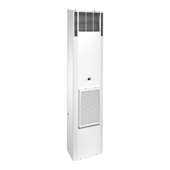
- Page 1 嵌入式机柜空调操作及使用说明书 DTI 8000ES 系列 Operating and assembly instruction For built-in cooling units DTI 8000ES...
-
Page 2: Table Of Contents
1 手册提示 ................................4 2 搬运 ..................................4 2.1 运输 ..................................4 2.2 储运 ..................................4 2.3 开箱 ..................................4 3 供货范围 ................................5 4 一般信息 ................................5 5 铭牌 ..................................5 6 安全 ..................................5 7 功能 ..................................6 7.1 配置与功能... - Page 3 13.1 清洁 ..................................18 13.2 维护 ..................................18 14 停止使用 ................................18 15 故障排除 ................................18 16 保障条款 ................................19 附表 I ..................................20 1 HINTS ON THE MANUAL ..........................21 2 HANDLING ................................21 2.1 Transport ....................................21 2.2 Storage ....................................21 2.3 Unpacking ..................................22 3 SCOPE OF DELIVERY AND OPTIONS ......................22 4 GENERAL INFORMATION ..........................22 5 NAME PLATE ..............................22 6 SAFETY ................................23...
- Page 4 11.3 Start-up / Test mode ................................34 11.4 Unit characteristics ................................34 11.5 Door contact ..................................34 11.6 Equipment fault ................................35 11.7 Self-check function ................................35 11.8 Setting possibilities ................................35 12 PARAMETERS VIEW AND SETTINGS ........................35 13 CLEANING AND MAINTENANCE .........................36 13.1 Cleaning ...................................36 13.2 Maintenance ..................................37 14 STOPPING USING ...............................37 15 TROUBLE SHOOTING ............................37...
-
Page 5: 手册提示
请在安装机组前完整仔细阅读此手册。 本手册构成标准供货不可分割的一部 分,必须保存至机组报废为止 1 手册提示 此手册为百能堡电气科技有限公司(以下简称百能堡)提供的门装或侧装螺栓固定,外挂式机柜空调系列的安 装运行指南。 提示: 每台机柜空调的技术规格及安装、连接和操作相关信息也可在随机附带的单独文件中查询。本手册中,安全提 示和其他信息以下形式出现: 危险! 如果没有严格遵守所述的措施,将有生命危险或造成健康危害。 危险! 如果没有严格遵守所述的措施,将可能因电击造成生命或健康危害。 注意: 如果没有严格遵守所述的措施,将有可能造成生命财物损失。 提示: 提示包含关于所述措施或指导的额外信息。 2 搬运 2.1 运输 • 只能通过壳体或吊环来提升机柜空调(M8吊环不在供货范围)。 • 运输时保持机柜空调处于最终使用时相同的摆放状态。 • 如果整体机柜需要运输,请在运输前将机柜空调拆下并单独包装。 不按照这些指导操作,将导致保障条款失效。 2.2 储运 • 储存环境不应超过70℃。 • 储存时使机组处于最终使用时的摆放状态。 不按照这些指导操作,将导致保障条款失效。 2.3 开箱 • 开箱过程中应当仔细查看机柜空调,看是否存在因运输造成的破坏,尤其注意是否有部件松动、凹坑、擦伤和 漏油等。任何损坏应当立即通知承运商(根据“损坏规则”指示),并且适用“百能堡产品售后服务声明“的最新版... -
Page 6: 供货范围
3 供货范围 供货范围包括: • 机柜空调 • 附件包(包括紧固件,插头式电气连接器等) • 特殊的附件(如适用) • 技术规格书 • 使用说明书 4 一般信息 • 百能堡可以妥善处理旧设备,但客户需承担运输费用. • 百能堡生产的机柜空调不含以下物质: - 多氯三联苯 - 石棉 - 甲醛 - 镉 - 液态有害物质 • 对每台机柜空调进行检查以确保它是完全依照9.ProdSV的规定(德国事故预防法规)。 • 交货前百能堡已对每台空调在工厂进行电气安全检测。 5 铭牌 安装和维护,请注意机器背部铭牌标注的详细技术信息。 6 安全 • 由百能堡生产的机柜空调是专为机柜散热(IP54)而设计的。 •... -
Page 7: 配置与功能
• 任何其他使用范围被视为非授权使用, 并将不作保修承诺。电气设备应定期检查。任何异常如连接松脱或烧 焦的电缆必须被立即修复。 • 只有专业技术人员才能对热交换系统和电气部件进行操作。 • 请务必遵守相应的安全和环保法规。 危险! 任何清洁或维护操作之前,需切断机柜空调电源。 只有原厂备件可以使用。 7 功能 7.1 配置与功能 设备配置: 1) 高品质关键零部件 2) 压缩机保护装置 3) 智能控制系统 4) 冷凝水蒸发器 (可选) 5) 2~400V交流供电(可选) 设备功能: 1) +15℃~+55℃外部环境温度 2) 内部控制温度 +25℃~+45℃ 3) 上电自检和运行中实时自检 4) 冷凝水蒸发器(可选) 5) IP54/IP34防护 6) 2~ 400V交流供电(可选) 注意:... -
Page 8: 技术规格书
• 带冷凝水蒸发器(可选)的制冷设备在正常情况下,可以蒸发掉水分。但为防止蒸发器故障后产生的冷 凝水溢流,请连接冷凝水管路,然后再通过水管排出。始终确保冷凝水正确地排出。在特定情况下有可能会 发生凝结水过量,例如,机柜不密封或机柜内部温度经常低于露点温度。 注意: 在正常运行过程中发生冷凝水过量,请检查机柜的密封。 我们建议安装一个门接触开关,当机柜门被打开时,机柜空调将自动关闭,以防止过度冷凝水。 8 技术规格书 8.1 电气原理图 8.2 备品备件 685408028A... -
Page 9: 安装开孔
请使用百能堡物料号来采购备用件 备用件 8031ES 8041ES 内风机 18861100017 18861100018 外风机 18861100017 18861100019 压缩机 18861200003 18861200007 内风机电容 18864000004 18864000006 外风机电容 18864000004 18864000001 压缩机电容 18864000009 18864000013 过滤干燥器 18865000002 18865000002 物料号位于控制器上 控制器 8.3 安装开孔 DTI 8031ES (空调外形 ) 685408028A... - Page 10 DTI 8041ES 685408028A...
-
Page 11: 技术参数
8.4 气流原理 嵌入式安装门 外循环出风 外壳 内循环进风 电器连接 指示装置 内循环出风 外循环进风 注意: 在安装此设备前应当完整仔细地阅读此说明。此说明是设备不可分割的一部分,在设备报废请前务必保留。 安装前,请确认设备间以及设备至墙体的距离至少有 200 毫米的间距;在柜子内部的进风 以及出风 没有干 涉以及障碍。 8.5 技术参数 685408028A... - Page 12 DTI 8031ES 性能 制冷能力 A35/A35 * 500 / 530 W 制冷能力 A50/A35 * 285 / 330 W 冷媒* R 134a 冷媒量* 200 g 温控(工厂设置) +35°C +95°F 内部温度报警指示(工厂设置) > +50°C +122°F 环境温度 +15°C +59°F . . . +55°C +131°F 内部温度 +25°C +77°F . . . +45°C +113°F 外循环气流量...
- Page 13 DTI 8041ES 性能 制冷能力 A35/A35 * 800 / 900 W 制冷能力 A50/A35 * 550 / 650 W 冷媒 * R 134a 冷媒量* 300 g 温控(工厂设置) +35°C +95°F 内部温度报警指示(工厂设置) > +50°C +122°F 环境温度 +15°C +59°F . . . +55°C +131°F 内部温度 +25°C +77°F .
-
Page 14: 安装工作
铭牌信息 无过滤网(可选)情况下制冷量 ° 自由送风 °° 空调电器接 处另需电器 子空间40mm 9 安装 9.1 概述 • 正确选择机柜空调在机柜上的安装位置,保证良好的通风。 • 机柜空调之间或是机柜空调和墙壁的距离必须保证至少200毫米。 • 在机柜内部,空调的电器连接 子处需预留至少40mm空间. • 在机柜内部,电气元件不得阻碍空气循环。 • 机柜空调在安装时,机柜空调的电源必须断开! • 安装现场必须受到保护,免遭污染。 注意: 如果机柜空调是装在机柜门上,必须检查门的铰链能够支持机柜空调的重量或当门被打开机柜时,不会翻倒。 注意: 金属碎屑可能损坏机柜。 如果在安装现场开安装孔,确保使用保护罩,以免切屑进入机柜,损坏电气元件。 提示 为方便机柜空调安装,M8的吊环可以旋入机柜空调顶部固定,方便吊装,简单“一人安装”就能实现。 9.2 安装工作 内嵌式空调安装 机柜安装面要开好空气通风 和螺栓安装固定孔, 根据随机组所附图纸。所附图纸同时说明了电气连接接 位置和通风 位置。 1) 如机柜未预留机柜空调的开... -
Page 15: 电气连接
1 机柜空调组 5 弹簧垫片 2 机柜侧 或机柜门 6 密封条 3 安装卡扣 7 螺栓 4 平垫片 8 密封条 6)如果机柜空调在安装时拆下外壳顶部的M8螺母,需将其安装好。 7) 将电线按照接线图(见机柜空调背部)连接到连接头(附件包中),并连接到机柜空调。 :1.0 – 2.5平方毫米或AWG18 - AWG14 - 导线 (在电缆的大小选择,应参照相关法规要求!) 8) 将机柜空调插上电源(见9.3) 不同机器可能安装方式不同,请参考随机资料。 9.3 电气连接 注意: • 机柜空调应当经由断路器连接到电源(请选择合适的断路器),断开断路装置时,其触点间隙应不少于3毫米。 • 电源线上不可以串接温度传感器。 • 电源线上需要串接铭牌注明的保险丝,作为线路保护。 •... -
Page 16: 运行条件
一般空调的额定电压230V或400V。 门触点: 为了避免任何破坏性的影响,建议使用一根带护线套的双绞线电缆。 警告 无需另接外部电源。 如果门触点开关未被使用,需将其短接。 故障指示 对于故障信号指示有1对连接触点可使用(见技术附页线路图) 故障信号线安装不受到任何特殊要求限制。 警告 故障指示连接最大容量为: 230V,1A 10 运行条件 • 电压范围为额定电压的 ± 10%以内。 • 电源频率为额定频率的 ±3Hz以内。 • 环境温度必须低于55℃。 • 使用本机时注意使热交换量适合实际的需求。 • 只使用原装备件。 11 投入使用和功能 • 机柜空调包含的功能及可选项见章节 11.1 概述 • 机柜空调配有温度控制系统。机柜内部温度通过温度传感器来测量。通过操作显示器可以设定不同的机柜内 温度(见附表)。 • 机柜空调具有上电检测、运行时实时监测功能。上电检测过程中如果有故障,空调会发出相应的报警,这使 得在进入工作模式之前更方便的排查设备故障。 警告 机柜空调只能在装有前盖的情况下运行,否则会因散热不良造成机柜空调被损坏。... -
Page 17: 门触点
模式 时间曲线 特征 t=0s-3s 无功能,操作显示 启动模式 器显示“0.0℃” t=3s-30s 显示内部温度 t=30s-40s 内风机运行 t=40s-50s 外风机运行 内风机停止 t=50s-80s 测试模式 压缩机运行 外风机停止 t=80s-140s 内风机、外风机、 压缩机一起运行 11.5 门触点 确保安全门限位开关应连接到指定 (见机壳上线路图或附件)当打开机柜门时门触开关即被断开,机柜 空调所有马达延时依次关闭,之后产生报警。 11.6 设备故障 机柜空调故障触点X54—1,2脚为常闭触点,上电后无故障为闭合,有故障时将引起故障触点断开并显示告警 代码(见章节15)。 11.7 自检功能 • 机柜空调具有开机自检和运行中实时自检功能。 • 开机自检即启动测试模式(见11.3、11.4)。 • 实时自检允许设备在正常运转中实时监测是否有异常发生,并及时上报。 11.8 设置的可能性 机柜空调可通过操作显示器来选择柜内不同设定温度以及参数。(见章节12)... -
Page 18: 清洁和维护
指示灯 指示灯含义 长亮 闪烁 操作面 ----- 上电自检 自检 ----- 制冷 正在制冷 ----- ----- 制热 ----- ----- 除湿 ----- 外风机 风机运转 ----- 告警 告警发生 1. 参数查看 主界面下,按“Select”键 3S,进入界面“SEE”,再按 “Select”键确认进入,按 “▲”或“▼”键可循环选择柜内回风温度“Pb1”、空调启动温度“t1”、门禁开 关状态“dor”、内风机运行状态“IFR”、外风机运行状态“EFR”、压缩机运行状态“Con”、报警输出状态 “ALr”,在任意一个参数代码界面按“Select”键,显示相应参数的参数值,按“Mode”键返回上层菜单或者 静置 5min 自动返回主界面。 具体代码意义详见(附表一)。 2. 参数设置 主界面下,按“Select”键 3S,进入界面“SEE”,再按“Select”键确认进入后,通过“▲”“▼”键选择 “t1”,再按“Select”键显示具体参数值,长按“▲”键 6S 后即可调整参数值的大小,调整到正确的数值 后再次按“Select”键确认修改,然后按“Mode”键返回上层菜单或者静置... -
Page 19: 停止使用
13.1 清洁 机柜空调在正确使用条件下做到了最大可能的免维护,即不需要定期检查维护。如果有条件定期对冷凝回路 进行清洗,将提高设备的运转效率以及可靠性。 特别注意以下说明: • 清洗外部风道,冷凝器以及外风机。 • 用软刷或高压空气进行作业。 步骤如下: 1)断开机柜空调电源。 2)打开外壳。 3)清洁风道。 4)清洁外风机。 5)清洁交换器。 6)装回外壳 7)接通电源并观察上电自检,确保设备运转正常。 注意:防止电气元件漏电。不要使用任何尖锐或锋利的物体。 注意:防止热交换器损坏。 注意:防止外罩电气连接损坏。 在拆卸外罩时,应当手动拔去外罩里面的电气连接。安装时,不要忘插上该电气连接! 13.2 维护 设备出现故障后,会自动提示故障代码,主要故障代码对应的故障原因 见章节 15 。 在每一次维护后,请等待设备上电自检结束,查看自检情况,以确保设备能够正常运转。 14 停止使用 如果机柜空调在较长时间内未被使用,请切断电源。确保未经授权的人员不会擅自启动空调。 机柜空调需要报废处理时,需根据相关环保法规由专业人员进行处理。(见章节 4) 15 故障排除 尽管有精心维护,还是有可能产生故障。机柜空调的实时自检功能能够准确的自行诊断设备故障。 如果机器发生故障,操作显示器显示相关报警代码,用户可根据下表中的报警代码查找,使得诊断更容易。 685408028A... -
Page 20: 保障条款
报警列表 报警代码 描述 故障排除方法 1)检查感温头 Pb1; 2)检查连接线是否损坏; AL01 Pb1 报警 3)检查接头是否插错位。 1) 检查门开关; AL02 机柜门打开 2)检查接线是否松动; 3)检查接线是否接错。 1)查看是否 AL02 报警,此时设备停止工作; 2)检查内外风机是否正常工作; 3)检查压缩机是否正常工作; AL03 超温告警 4)检查冷凝器是否脏堵; 5)检查内部风 是否堵塞,风道是否顺畅; 6)检查热负荷。 警告:非授权人员不可检修此设备 16 保障条款 以下情况保障将失效: · 机组的不恰当使用,不适宜的运行条件或不遵守操作指导; · 在腐蚀或酸性空气环境下使用; · 由脏污或脏堵的过滤垫造成的损坏; · 非授权人员擅动温度控制回路,改动机组或更改机组序列号; ·... -
Page 21: 附表 I
附表 I 显示参数(操作显示器) 参数 描述 最小值 最大值 默认 单位 内循环回风温度 ℃ 值 启动温度 ℃ 门开关,0 代表门开关断开,1 代表门开关闭合 内风机,0 代表停止工作,1 代表正在工作 外风机,0 代表停止工作,1 代表正在工作 压缩机,0 代表停止工作,1 代表正在工作 故障报警,0 代表有故障输出,1 代表无故障,设备正常工作 AL01 Pb1 报警,0 代表有故障,1 代表无故障 AL02 机柜门打开,0 代表有故障,1 代表无故障 AL03 超温告警,0 代表有故障,1 代表无故障 * 为客户可改参数。... -
Page 22: Hints On The Manual
1 Hints on the manual This handbook contains instructions for the installation and operation of door and side-mounted, bolt-on Cooling Series Units provide by Pfannenberg (PCN). Hint The technical specifications for each machine along with additional information on assembly, connections and operation are contained in a separate sheet. -
Page 23: Unpacking
Especially pay attention to loose parts, dents, scratches, visible loss of oil etc. Any damage must be reported immediately to the forwarding agent (follow the instructions in "Rules for Damage Claims"). Moreover, the latest edition of the "Pfannenberg After Sales Service Declaration" shall apply. -
Page 24: Safety
6 Safety Cooling units produced by Pfannenberg are designed for application dissipating heat from switch cabinets (IP 54). The cooling unit is only suitable for installing on the stationary operation. Only the authorized specialist can be work on the cooling system and electrical components. -
Page 25: Operating Principles
Please refer to the attached technical specification for the details function of the cooling unit. 7.2 Operating principles ss s s s. ( ) f ( ) s ( ). 7.3 Condensate The condensate is discharged in the following way: In case of normal condensate drainage a reservoir (option) collects the condensate which is then drained by means of a hose. -
Page 26: Circuit Diagram
8.1 Circuit Diagram 8.2 Spare parts Please order your spare parts only with the Pfannenberg-parts-number. Spare parts 8031ES 8041ES Internal fan 18861100017 18861100018 External fan 18861100017 18861100019 18861200003 18861200007 Compressor 18864000004 18864000006 Internal fan capacitor 18864000004 18864000001 External fan capacitor... -
Page 27: Installation Hole
8.3 Installation Hole DTI 8031ES 685408028A... - Page 28 DTI 8041ES 685408028A...
-
Page 29: Airflow Principle
8.4 Airflow principle Caution: Read this manual completely and carefully before installing the unit. This manual is an integral part of the scope of delivery and must be kept until the unit is disposed of. Prior to mounting, ensure that the clearance of the units to each other and to the wall is at least 200mm; air inlet and outlet are not obstructed on the inside of the enclosure. - Page 30 Cooling data DTI 8031ES y s ) ° (+ °F) . (f y s ) > + ° (+ °F) ° (+ °F) . . . + ° (+ °F) ° (+ °F) . . . + ° (+ °F) °) ³...
- Page 31 Cooling data DTI 8041ES y s ) ° (+ °F) . (f y s ) > + ° (+ °F) ° (+ °F) . . . + ° (+ °F) ° (+ °F) . . . + ° (+ °F) °) ³...
-
Page 32: Installations
°) f °°) 9 Installations 9.1 General • ’s cooling unit. • must be keep the distance at 200mm at least for the single units or the unit and the wall. • ’s not impede air circulation in the internal cabinet. •... -
Page 33: Electrical Connection
1 Cooling unit DTI 5 springs shim 2 switch cabinet wall or door 6 sealing strip 3 snap-fastener 7 bolts 4 flat gasket 8 sealing strip s f x 5) It 6) Clamp s z : . 7) P . (s ss y 9.3 Electrical connection Caution:... -
Page 34: Operating Condition
Caution: . ’s s 230V or 400V. Door contact: Caution: No external voltage may be applied Fault indication: Caution: The contact may be loaded with max230V, 10 Operating condition • ± % • ± Hz f • ℃. •Us •Us 11 Putting into operation and function Please 11.1 General remarks... -
Page 35: Operate The Display
11.2 Operate the display y. “0.0℃” s 3s after the supply power is switched on, then internal temperature is shown. This indicates the unit works properly. If there is a failure or y’s it easier to diagnose the cooling unit. (Refer to section 15) 11.3 Start-up / Test mode ’... -
Page 36: Equipment Fault
11.6 Equipment fault — 11.7 Self-check function . & . ) 11.8 Setting possibilities Caution: 12 Parameters View and Settings • 1. View Parameters 685408028A... -
Page 37: Cleaning And Maintenance
ss ” ” f s “ ” ss ” ” ”▲” “▼” : ” ” ” ” ” ” “ FR” “ FR” “ ” “ L ” ss ” ” P ss “M ” 2. Parameter setting s “ ” ss ”▲”... -
Page 38: Maintenance
Caution: Caution: ’ Caution: 13.2 Maintenance k s f 14 Stopping using s. ( 15 Trouble shooting Alarm codes list: Alarm code description Trouble shooting method ) M k s ) M k s ) M k s 685408028A... -
Page 39: Warranty Conditions
) M k s ) M k s f ’s Caution: 16 Warranty Conditions • • f • • f • •F • • •R s; s 685408028A... - Page 40 Appendix I Parameter Description Min. Max. Default Unit ℃ Air return of inner cycle ℃ * T1 Internal setting temperature Door switch, 0 means open, 1means close Internal fan, 0 means OFF, 1 means ON External fan, 0 means OFF, 1 means ON Compressor, 0 means OFF, 1 means ON Alarm, 0 means alarm output, 1 means units work normal...
- Page 41 百能堡电气科技(苏州)有限公司 中国苏州工业园区杏林街 108 号 邮编:215026 电话:+86-512-6287-1078 传真:+86-512-6287-1077 邮箱:service@pfannenberg.cn http://www.Pfannenbergchina.com Pfannenberg Electro-Technology (Suzhou) Co.,Ltd. No. 108 Xinglin street, SIP, Suzhou 215026, Jiangsu, P.R.C Tel: +86-512-6287-1078 Fax: +86-512-6287-1077 e-mail: service@pfannenberg.cn http: //www.pfannenberg.cn 685408017 /11-2017...
Need help?
Do you have a question about the DTI 8000ES and is the answer not in the manual?
Questions and answers