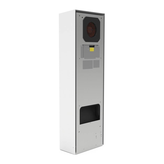
Pfannenberg DTS Series Operating Manual
Attachment and installation cooling units multi controller (mc) – 400 / 460 v, 3~
Hide thumbs
Also See for DTS Series:
- User manual ,
- Operating manual (217 pages) ,
- Operating and installation instructions (52 pages)


Need help?
Do you have a question about the DTS Series and is the answer not in the manual?
Questions and answers