Advertisement
Quick Links
Advertisement

Subscribe to Our Youtube Channel
Related Manuals for Mounting Dream MD5425


Summary of Contents for Mounting Dream MD5425
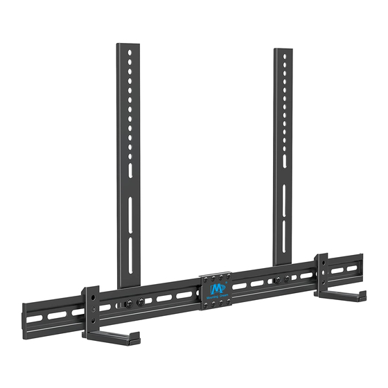
- Page 1 MD5425 INSTALLATION INSTRUCTION (C3)
-
Page 2: Safety Caution
● For wall mounted cases, the wall must be capable of supporting five times the weight of the TV, mount and sound bar combined. ● Incorrect installation may result in product damage or body injury. Mounting Dream shall bear no responsibility for any damage or injury resulted from incorrect installation, incorrect assembly or misuse. - Page 3 Parts and Hardware WARNING: This product contains small items that could be a choking hazard if swallowed. Before starting assembly, verify all parts are included and undamaged. NOTE: Not all hardware included will be used. Connection plate Allen Key M5x8mm Bolt Wall plate Assemble Wall plate Wall plate unit...
- Page 4 Parts and Hardware M6x10mm M6 Washer TV Screws Soundbar Screws M6x16mm M6x25mm M4x16mm M5x16mm Bracket Bracket (Left) (Right) M8x45mm M8x25mm M6x16mm Spacers Washers M8x10mm 2.5mm "L" Shaped Bracket Lag Bolt M7x55mm 2pcs Concrete Wall Anchor 2pcs Install on TV Wall Mount 2A-1 Attach Brackets to Wall Plate Horizontal distance of TV mounting holes...
- Page 5 2A-2 Disassemble Your TV from the Mount Ⅰ Remove all cables Ⅱ Take off the TV Ⅲ Remove the TV from the mount brackets from your TV 2A-3 Attach the Assembled Brackets Unit to Your TV Tips: No need to use washer (g) when using M8 screw (c/d).
- Page 6 2A-4 Hang the Whole Assembled Unit to the Mount 2A-5 Hang and Secure the 'L" Shaped Brackets 2A-6 Put the Soundbar on the "L" Shaped Brackets Back hole Bottom hole...
-
Page 7: Wood Stud Installation
Mount on the wall For wood stud installation, follow Option 1 For concrete installation, follow Option2 on PAGE 7 Wood Stud Installation <16mm Min. Wood Stud Size: (5/8") nominal 4"(102mm) Max. actual 3 1/2"(89mm) 16"(406mm) Min. Wood Stud Size: nominal 2"(51mm) actual 1 1/2"(38mm) Centre line 16"(406.4mm) - Page 8 CAUTION: To avoid potential personal injury or property damage: All 2 lag bolts MUST BE firmly tightened to prevent unwanted movement of the wall plate assembly. Ensure the wall plate assembly is securely fastened to the wall before continuing on to the next step.
- Page 9 CAUTION : To avoid potential personal injury or property damage: All 2 lag bolts MUST BE firmly tightened to prevent unwanted movement of the wall plate assembly. Ensure the wall plate assembly is securely fastened to the wall before continuing on to the next step.
Need help?
Do you have a question about the MD5425 and is the answer not in the manual?
Questions and answers