
Related Manuals for ICP DAS USA iSN-101

Summary of Contents for ICP DAS USA iSN-101
- Page 1 / iSN-104 Liquid Leak Detection Module User Manual iSN-101 iSN-101/DIN iSN-104 Version: 2.3.0 Date: Dec. 2022 Edited by Jerry Tseng...
- Page 2 Warranty All products manufactured by ICP DAS are warranted against defective materials for a period of one year from the date of delivery to the original purchaser. Warning ICP DAS assumes no liability for damages consequent to the use of this product. ICP DAS reserves the right to change this manual at any time without notice.
-
Page 3: Table Of Contents
3. Configuration via RS-485 ....................19 Appendix A: DCON Command Sets ..................26 A-1. iSN-101/104 DCON Command Sets ................ 26 Appendix B: ModbusMasterToolPC ..................31 Appendix C: Modbus Address Table ..................35 C-1. iSN-101/104 Modbus Address Mappings (Base 1) ........... 35 Revision History ........................38... -
Page 4: Introduction
1. Introduction The iSN-101/104 Liquid Leak Detection Module is a low-cost intelligent liquid leak detection device that iSN-101 can be used to directly control Relay Output. No additional conversion module is needed and the iSN-101/104 can be easily integrated with a variety of monitoring systems to achieve remote alarm and remote device control. - Page 5 - 5 - iSN-101/104 User Manual...
- Page 6 Features Leak detection triggers and audible alarm Open wire detection triggers and audible alarm (iSN-101 Only for after 2021,Q1(FW:A1.3 or later) and used with CA-LLD-DC100X-Lxxx + CA-LLD-DC100X-TR to have Open wire detection. ) A mute button to silence the alarm...
-
Page 7: Hardware
Input Voltage Range +10 ~ +30 VDC Consumption 1.5 W Max. 1.6 W Max. Mechanical Dimensions (L x W x H) 83 mm x 70 mm x 29 mm 72 mm x 95 mm x 57mm - 7 - iSN-101/104 User Manual... -
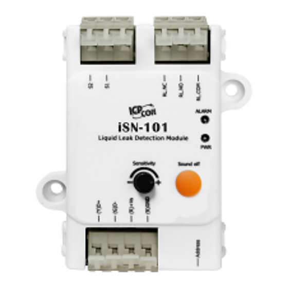
Page 8: Appearance & Settings
The two LED indicators from up to down are: Alarm: red for leak alarm condition. blinking red for open wire alarm condition. *(iSN-101 Only for after 2021,Q1(FW:A1.3 or later) and used with CA-LLD-DC100X-Lxxx + CA-LLD-DC100X-TR to have Open wire detection. ) PWR: green for normal operation. - Page 9 1-ch Input Insert Leader Cable. As cable termination is not polarity conscious DIP Switch Address Relay Output Wire Connection: Output Type ON State OFF State Readback as 1 Readback as 0 Relay Output - 9 - iSN-101/104 User Manual...
-
Page 10: Isn-104 Appearance
LED blinking for open wire alarm condition. PWR: Power LED. Audible alarm 70 dB Audible alarm with silence button Sensitivity Adjustment Sensitivity Adjustment Range: 26KΩ ~ 580KΩ 4-ch Input Insert Leader Cable. As cable termination is not polarity conscious - 10 - iSN-101/104 User Manual... -
Page 11: Connector For Power/ Rs-485 / Liquid Leak Detection Cable / Relay Output
DIP Switch Address 2.3 Connector for Power/ RS-485 / Liquid Leak Detection Cable / Relay Output - 11 - iSN-101/104 User Manual... - Page 12 The fool-proofing groove (as red circle) is useful for easy connection of Liquid Leak Detection Plug and Leader Plug. Please make sure they are located in the same direction when connecting these two items. Leader Plug Liquid Leak Detection Plug Make sure to tighten firmly - 12 - iSN-101/104 User Manual...
- Page 13 Connect the Leakage Probe with Wires Take off cover Put wire and tighten the screw down - 13 - iSN-101/104 User Manual...
-
Page 14: Pin Assignments
Put cover back Install the two mounting screws into the 2 keyhole mounting holes. 2.4 Pin Assignments iSN-101 iSN-104 - 14 - iSN-101/104 User Manual... -
Page 15: Wire Connections
2.5 Wire Connections iSN-101/104 User Manual - 15 -... -
Page 16: Application
Liquid Leak Detection Cable can even be fixed directly to the water supply and return lines. Liquid Leak Detection Cable is suitable for larger surface areas with multiple leak points. Liquid Leak Detection wires Polymer carrier Continuity wires Liquid forming current loop trigger alarm - 16 - iSN-101/104 User Manual... - Page 17 Terminal Resistor Terminal Resistor open wire status trigger alarm Liquid forming current loop trigger alarm *(iSN-101 Only for after 2021,Q1(FW:A1.3 or later) and used with CA-LLD-DC100X-Lxxx + CA-LLD-DC100X-TR to have Open wire detection. ) Server Room Floor Water supply Leakage Probe Leakage Probe are designed to detect leaks at specific locations and specific water levels.
-
Page 18: Dimensions (Unit: Mm)
Leakage Probe 2.7 Dimensions (unit: mm) iSN-101 - 18 - iSN-101/104 User Manual... -
Page 19: Configuration Via Rs-485
Response Delay (ms): 0 Note If there are multiple iSN-101/104 connected to the same RS-485 network, each module needs be set with a unique RS-485 address. More than one module having the same address will cause communication failure Testing RS-485 Communication 1. - Page 20 2. Launch the DCON_Utility_Pro.exe. Stop Search Start Search Set COM port Configuration 3. Click the icon to configure the COM port. 4. Select the COM Port number used to connect the iSN-101/104 logger. - 20 - iSN-101/104 User Manual...
- Page 21 5. The Baud Rate is factory default to 9600 bps. 6. Select the Protocol tab. 7. Select the Format tab and check the parity that set in the logger. - 21 - iSN-101/104 User Manual...
- Page 22 8. Click the Start Search icon. 9. The iSN-101/104 logger searched out will be listed as below. 10. Click the module name to configure the logger. Note The Protocol/Baud Rate/Parity/Checksum items marked with ”(INIT*)” means that when any of those items needs be modified, the pin 4.INIT needs to be set in ON position and power cycle the logger, then the item can be modified.
- Page 23 Leak Alarm Mode & Status Leakage Detect Resistance Open Wire Alarm Mode & Status (iSN-101 Only for after 2021,Q1(FW:A1.3 or later) and used with CA-LLD-DC100X-Lxxx + CA-LLD-DC100X-TR to have Open wire detection. ) Select one of the radio button and the...
- Page 24 Alarm status. In case an Alarm occurs, the relay turns ON, it can be used to turn on the user’s alarm light or beeping alarm or other device. - 24 - iSN-101/104 User Manual...
- Page 25 - Change DCON configuration such as baud rate, parity and checksum - Communication failure with a iSN-101/104 module. When a iSN-101/104 module is powered-on with the pin 4.INIT in ON position, the protocol is DCON, address is 0, Baud Rate is 9600 bps, Parity is set to N/8/1 and Checksum is disabled.
-
Page 26: Appendix A: Dcon Command Sets
Appendix A: DCON Command Sets A-1. iSN-101/104 DCON Command Sets Command Description Read All Analog Inputs response iSN-101: >(resistance in k ohm)(threshold index by VR) in engineering format iSN-104: >(resistance of ch0 in k ohm)(resistance of ch1 in k ohm)(resistance of... - Page 27 = 0 to 3 for leak alarm, 4 to 7 for open wire alarm of channel 0 to 3 @AADI Read DI & DO Response !AA0OOII @AADOhh Set DO (For iSN-101 Only) @AAEATCi* Enable AI alarm of channel i, T->M: momentary alarm, L: latched alarm iSN-101: i = 0 for leak alarm...
- Page 28 Read INIT status $aaM Read module name $aaPN Set Modbus RTU/DCON protocol $aaP Read Modbus RTU/DCON protocol $aaS1 Reload factory calibration parameters ~aaAi Read ADC raw data ~aaE0 Disable calibration ~aaE1 Enable calibration ~aaI Soft INIT - 28 - iSN-101/104 User Manual...
- Page 29 ~aa4 Read power on and safe DO Response !AAPPSS ~aa5PPSS Set power on and safe DO *Note:DCON firmware must be version A103 or later with Terminal Resistor supports open wire function. (for iSN-101 only) - 29 - iSN-101/104 User Manual...
- Page 30 00: no parity, 1 stop bit 01: no parity, 2 stop bits 10: even parity, 1 stop bit 11: odd parity, 1 stop bit Data Format Setting (FF) Bit 6 0: checksum disabled 1: checksum enable - 30 - iSN-101/104 User Manual...
-
Page 31: Appendix B: Modbusmastertoolpc
ModbusMasterToolPC is a free, easy-to-use tool for Modbus communication and diagnosing the wiring. It is located in the company CD: CD:\ Napdos\iSN-101/104\utility\ and needless to install This section intends to guide the steps for creating the Modbus communication with iSN-101/104 logger. - Page 32 4. Select Connect in the Connection menu. 5. Select the communication interface. When using RS-485 as the interface, select the COM port, check the RTU mode and click on the OK button. 6. Select Definition in the Setup menu. - 32 - iSN-101/104 User Manual...
- Page 33 7. Select the Modbus function code, input the start address and length, and click on the OK button. 8. Read data. - 33 - iSN-101/104 User Manual...
- Page 34 1. Highlight the Modbus address in the Holding Register or Coil Status list 2. Select Set Value in the Setup menu. 3. Input the data in the Value box and click on the OK button - 34 - iSN-101/104 User Manual...
-
Page 35: Appendix C: Modbus Address Table
Appendix C: Modbus Address Table C-1. iSN-101/104 Modbus Address Mappings (Base 1) Address Description Attribute 30001 ~ Resistance of sensor 0 to 3 in 100 ohm (iSN-101:0) 30004 40001 ~ 40004 30002 Leak threshold index by VR, 0 to 24(iSN-101) - Page 36 Write 1 to clear all high latched analog input values 00281 Write 1 to clear all low latched analog input values 00289 Low alarm status of leak sensor for iSN-101. Write 1 to clear low latched alarm.. - 36 - iSN-101/104 User Manual...
- Page 37 00290* Alarm status of open wire for iSN-101. Write 1 to clear latched alarm. R/W 00289 ~ Leak alarm status of leak sensor 0 to 3 for iSN-104. Write 1 to clear 00292 low latched alarm. 00293 ~ Open wire alarm status of leak sensor 0 to 3 for iSN-104. Write 1 to 00296 clear latched alarm.
-
Page 38: Revision History
Revision History Revision Date Description 1.0.0 2017/10 First released Add: open wire function 1.1.0 2021/11 (* iSN-101 for firmware version A103 and later only) Add: iSN-104 2.0.0 2022/02 Update 2.1.0 2022/08 Update Relay Output specification 2.2.0 2022/09 Update iSN-104 Modbus Address Table 2.3.0...
Need help?
Do you have a question about the iSN-101 and is the answer not in the manual?
Questions and answers