Table of Contents
Advertisement
Quick Links
Advertisement
Table of Contents

Related Manuals for NIVELCO NIPRESS D-B00 Series


Summary of Contents for NIVELCO NIPRESS D-B00 Series
- Page 1 drcbr44a0600p_02 1 / 20...
- Page 2 drcbr44a0600p_02 2 / 20...
-
Page 3: Table Of Contents
TABLE OF CONTENTS 1. INTRODUCTION ......................................4 2. ORDER CODE ......................................... 4 3. TECHNICAL SPECIFICATION ..................................5 3.1 DIMENSIONS ......................................7 3.2 ACCESSORIES ....................................... 9 3.3 SPECIAL CONDITIONS OF SAFE USE ..............................9 4. INSTALLATION ......................................10 ... -
Page 4: Introduction
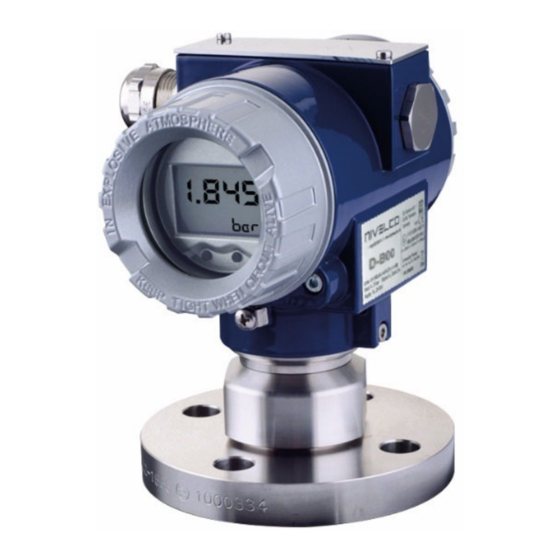
Thank you for choosing NIVELCO instrument. 1. INTRODUCTION NIPRESS D–B00 series pressure transmitters with ceramic flush sensor measure pressure and convert it into voltage and current output can be used in 2-wire systems. D-B00 has a really high overpressure resistance thanks to its Al 99.9% sensor. -
Page 5: Technical Specification
3. TECHNICAL SPECIFICATION Type DR–B– Measurement range 0…20 bar (0…290 psig) Overload capability According to the order code Accuracy ≥ 1 bar ±0.1%, p < 1 bar ±0.2% Medium temperature –25…+125 °C (–13 °F … +257 °F) Without display: –40…+70 °C (–40…+158 °F) Ambient temperature With display: –20…+70 °C (–4…+158 °F) Sensor... - Page 6 SPECIAL DATA FOR EX CERTIFIED MODELS ATEX approval, Ex ia Type DR–B–8Ex In case of stainless steel housing: Nominal process pressure > 10 bar: II 1G Ex ia IIC T4 Ga Nominal process pressure ≤ 60 mbar: II 2G Ex ia IIC T4 Gb Nominal process pressure >...
-
Page 7: Dimensions
3.1 DIMENSIONS DRC–B– DRF–B– Aluminum housing with display Stainless steel housing DRH–B– Flush sensor, ½" NPT internal sensor sanitary DIN 11851 DRP–B4– DRR–B4– Size DN40 DN50 ØA [mm] ØB [mm] 68.5 drcbr44a0600p_02 7 / 20... - Page 8 DRW–B–, DRZ–B– DRI–B–, DRQ–B–, DRU–B– flange flange Type DRW–B– DRZ–B– Type DRI–B– DRQ–B– DRU–B– Size 2" / 150 psi 3" / 150 psi Size DN25 DN50 DN80 D [mm] 152.4 190.5 D [mm] E [mm] 26.5 26.5 E [mm] 26.5 26.5 26.5 g [mm]...
-
Page 9: Accessories
3.2 ACCESSORIES - User’s and programming manual - Warranty card - EU declaration of conformity 3.3 SPECIAL CONDITIONS OF SAFE USE Before turning on the device, make sure the installation is complete, with no defects visible. The device may only be used within the limitations specified in the technical specifications. ... -
Page 10: Installation
4. INSTALLATION To enable the safe replacement of the instrument during operation the use of closing armature is recommended. A simple ball valve will be suitable for lower pressures and for higher pressures (above 6 bar) a three-way blow-off needle-valve can be suggested. In case of level measurement, it is advisable to screw the transmitter to the stump on the side of the tank. - Page 11 Installation steps: Tightening torques: ½" BSP: max. 10 Nm; 1" BSP: max. 20 Nm; 1½" BSP: max. 25 Nm; ½" NPT: max. 70 Nm. The specified tightening torques must not be exceeded! Do not use a pipe wrench, to avoid damaging the device! Installation steps for BSP process connection (DIN 3852): Do not use any additional sealing material such as Teflon tape! Check if the O-ring is intact, its surface even and clean and seat in the designated groove accurately.
-
Page 12: Wiring
5. WIRING In order to electrically connect the device with the connection terminals, the cover For devices with cable gland, make sure that the external diameter of the cable must be screwed off. used is within the allowed clamping range! Once connected the wires, tighten Use a shielded and twisted multicore cable for the electrical connection. -
Page 13: Hart ® Communication
® 5.1 HART COMMUNICATION The device can be configured using the keys, magnetic switches or by a HART ® communication device. In order to ensure the operation is flawless, the following requirements must be taken into account: Maximum cable length between measuring device and supply: where L maximum length of cable in [m], R resistance of cable... -
Page 14: Structure Of The Menu System
6.1 STRUCTURE OF THE MENU SYSTEM drcbr44a0600p_02 14 / 20... -
Page 15: Description Of The Menusystem
6.2 DESCRIPTION OF THE MENUSYSTEM The parameters can be set using three miniature keys, or the magnetic Set value: switches located under the metal cap. If a parameter is configured by providing a value, each digit must be configured The functions of these keys are as follows: separately. - Page 16 Menu list Description 2 CALIB Configuration of measuring range, display and output signal 2.1 ZERO Zeroing the display The message “CONFIRM” appears on the display when selecting the subsidiary menu item with the OK button. By pressing and holding the OK button for at least 2 seconds the zeroing is performed, and the message “CONFIRM”...
- Page 17 Menu list Description 3 SIGNAL Signal parameters 3.1 FUNCTION Function selection "LINEAR" (linear function) “2SQR” cut off 2% “2SQR3POW” “2SQR5POW” 3.2 DENSITY Input of the density Definable range: 100 ― 9999 kg/m Conversion is only applicable to the units [mFH], [cmFH] and [mmFH]. 3.3 DAMP Configuration of the damping Definable range: 0…100 s...
- Page 18 For security reasons it is necessary to enter the previous password to start the configuration. Confirm the value by the OK key. (The password is factory-preset to "0000".) Then set the new password and confirm it with the OK key. If you forgot your password, you may request for the master password, which is provided by the manufacturer, NIVELCO. 4.5 LANGUAGE Select DE for German or EN for English language 4.6 WPROTECT...
-
Page 19: Troubleshooting
7. TROUBLESHOOTING Fault Possible causes Fault detection / remedy Improper connection. Check the connections! No output signal: Broken conductor/wire. Check all wires using a cable tester! Defective measuring device (signal input). Check the ampere meter (and its fuse) and the analogue input of the signal processing unit! Load resistance too high. -
Page 20: Maintenance And Repair
(Returned Equipment Handling Form) must be filled and enclosed in the parcel. Download it from our website www.nivelco.com. The device must be sent back with a declaration of decontamination. A statement must be provided in the declaration that the decontamination process was successfully completed and that the device is clean from any hazardous substances.
Need help?
Do you have a question about the NIPRESS D-B00 Series and is the answer not in the manual?
Questions and answers