Table of Contents
Advertisement
Quick Links
Advertisement
Table of Contents

Related Manuals for NIVELCO NIPRESS D-A00 Series


Summary of Contents for NIVELCO NIPRESS D-A00 Series
- Page 1 drca344a0600p_02 1 / 24...
- Page 2 drca344a0600p_02 2 / 24...
-
Page 3: Table Of Contents
TABLE OF CONTENTS 1. INTRODUCTION ......................................4 2. ORDER CODE ......................................... 5 3. TECHNICAL SPECIFICATION ..................................6 3.1 DIMENSIONS ......................................8 3.2 ACCESSORIES ..................................... 10 SPECIAL CONDITIONS OF SAFE USE .............................. 10 4. INSTALLATION ......................................12 ... -
Page 4: Introduction
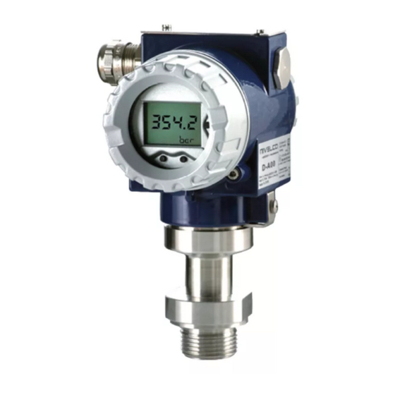
1. INTRODUCTION NIPRESS D-A00 series pressure transmitters with stainless steel internal or flush diaphragm measure pressure and convert it into voltage and current output can be used in 2-wire systems. D-A00 has been especially designed for the process food and pharmaceutical industries (version stainless steel field housing) and measures vacuum, gauge and absolute pressure ranges of gases, steams and fluids up to 600 bar (8700 psi). -
Page 5: Order Code
2. ORDER CODE ( NOT ALL COMBINATIONS POSSIBLE NIPRESS – A 4 – Measuring method / Range / overload Process connection Accuracy Code Code Code Code Output / Ex Code Temperature capability (bar) Relative / max. 125°C ¼" BSP 0 – 0.4 0.1% 4 –... -
Page 6: Technical Specification
3. TECHNICAL SPECIFICATION DR–A4– DJ–A4– DE–A4– DH–A4– Measurement range 0 – 600 bar (0 – 8700 psi) Overload capability According to the order code Accuracy ±0.1% Overpressure: -40 °C … +300 °C (-40 °F … +572 °F), Silicone oil filling fluid -40 °C …... - Page 7 SPECIAL DATA FOR Ex CERTIFIED MODELS ATEX approval, Ex ia (only for 4 – 20mA / 2-wire types): Type D–A–8 Ex, D–A–E Ex In case of stainless steel housing: II 1G Ex ia IIC T4 Ga, II 1D Ex ia IIIC T 85°C Da Ex marking In case of powder-coated aluminum housing: II 1/2G Ex ia IIB T4 Ga/Gb,...
-
Page 8: Dimensions
3.1 DIMENSIONS Aluminum housing with display Stainless steel housing drca344a0600p_02 8 / 24... - Page 9 DC–A4– DH–A4– DJ–A4– DJ–A4– DE–A4– Internal or flush sensor internal sensor Cooling element internal sensor BSP flush sensor DI–A4– DW–A4– DQ–A4– DZ–A4– DU–A4– Flange Flange Type DW–A4– DZ – A4 – Type DI–A4– DQ–A4– DU–A4– 2" / 150 psi 3"...
-
Page 10: Accessories
flush sensor, DV–A4– TriClamp Sanitary DIN 11851 VARIVENT (DN40/50) – P n ≤ 25 bar DT – A4– DL– A4– DM– A4– DN– A4– DO – A4 – DP – A4 – DR – A4 – 3.2 ACCESSORIES Size ¾"... - Page 11 Use exclusively Ex d IIC cable entry for devices with Ex d flameproof protection! For Ex d models, the cover must be secured against opening after the cover is closed by a safety locking screw! With 1/2 Ex marking device, the sensor membrane also serves as a partition between the Ex zones, therefore it must be protected against mechanical damage. ...
-
Page 12: Installation
4. INSTALLATION To create chance for replacing the instrument during operation, the use of closing armature is recommended. A simple ballcock valve will be suitable for lower pressures, but for higher ones (above 6 bar) a three-way blow-off needle-valve is suggested. In case of level measurement, it is advisable to screw the transmitter to the stump on the side of the tank. - Page 13 Installation steps: Tightening torques: ½" BSP: max. 10 Nm; 1" BSP: max. 20 Nm; 1½" BSP: max. 25 Nm; ½" NPT: max. 70 Nm. The specified tightening torques must not be exceeded! Do not use a pipe wrench, to avoid damaging the device! Installation steps for BSP process connection (DIN 3852) Do not use any additional sealing material such as Teflon tape! Check if the O-ring is intact, its surface even and clean and seat in the designated groove accurately.
-
Page 14: Wiring
5. WIRING In order to electrically connect the device with the connection terminals, the cover For devices with cable gland, make sure that the external diameter of the cable must be screwed off. used is within the allowed clamping range! Once connected the wires, tighten Use a shielded and twisted multicore cable for the electrical connection. -
Page 15: Hart ® Communication
® 5.1 HART COMMUNICATION The device can be configured using the keys, magnetic switches or by a HART communication device. ® In order to ensure the operation is flawless, the following requirements must be taken into account: Maximum cable length between measuring device and supply: where L maximum length of cable in [m], R resistance of cable together... -
Page 16: Structure Of The Menu System
6.1 STRUCTURE OF THE MENU SYSTEM drca344a0600p_02 16 / 24... -
Page 17: Description Of The Menusystem
6.2 DESCRIPTION OF THE MENUSYSTEM The parameters can be set using three miniature keys, or the magnetic Set value: switches located under the metal cap. If a parameter is configured by providing a value, each digit must be configured The functions of these keys are as follows: separately. - Page 18 Menu list Description 2 CALIB Configuration of measuring range, display and output signal 2.1 ZERO Zeroing the display The message “CONFIRM” appears on the display when selecting the subsidiary menu item with the OK button. By holding the OK button pressed for at least 2 seconds the zeroing is performed, and the message “CONFIRM”...
- Page 19 Menu list Description 3 SIGNAL Signal parameters 3.1 FUNCTION Function selection "LINEAR" (linear function) “2SQR” cut off 2% “2SQR3POW” “2SQR5POW” 3.2 DENSITY Input of the density Settable range: 100 ― 9999 kg/m Conversion is only applicable to the units [mFH], [cmFH] and [mmFH]. 3.3 DAMP Configuration of the damping Settable range: 0 ―...
- Page 20 "0000". Then set the new password and confirm it with the OK key. If you have forgotten your password, you may request the master password, which is provided by the manufacturer, NIVELCO. 4.5 LANGUAGE Select DE for German or EN for English language 4.6 WPROTECT...
-
Page 21: Troubleshooting
7. TROUBLESHOOTING Fault Possible causes Fault detection / remedy The Connection is improper. Check the connections! No output signal: Broken conductor/wire. Check all wires with cable tester! Defective measuring device (signal input). Check the ampere meter (and its fuse) and the analogue input of the signal processing unit! Load resistance too high. -
Page 22: Maintenance And Repair
8. MAINTENANCE AND REPAIR The instrument does not require regular maintenance. The repair should only be carried out at the NIVELCO' premises. When disconnecting the device, it must always be done in depressurized and disconnected state! Drain the medium before disconnecting the device. -
Page 23: Storage Conditions
9. STORAGE CONDITIONS Storage temperature: Without display: -40 °C ... +80 °C (-40 °F … +176 °F) With display: -30 °C … +80 °C (-22 °F … +176 °F) drca344a0600p_02 23 / 24... - Page 24 December 2020 NIVELCO reserves the right to change technical data without notice! drca344a0600p_02 24 / 24...
Need help?
Do you have a question about the NIPRESS D-A00 Series and is the answer not in the manual?
Questions and answers