Table of Contents
Advertisement
Quick Links
Advertisement
Table of Contents

Related Manuals for NIVELCO NIPRESS DD-400


Summary of Contents for NIVELCO NIPRESS DD-400
- Page 1 ddc4f52a0600p_01 1 / 17...
- Page 2 ddc4f52a0600p_01 2 / 17...
-
Page 3: Table Of Contents
TABLE OF CONTENTS 1. INTRODUCTION ......................................4 2. ORDER CODE (NOT ALL COMBINATIONS POSSIBLE!) ..........................4 3. TECHNICAL SPECIFICATION ..................................5 3.1 DIMENSIONS ......................................6 3.2 ACCESSORIES ....................................... 6 3.3 SPECIAL CONDITIONS OF SAFE USE ..............................6 ... -
Page 4: Order Code (Not All Combinations Possible!)
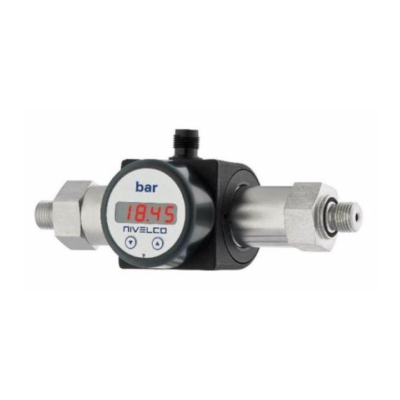
1. INTRODUCTION NIPRESS DD-400 series differential pressure transmitters work in a 3-wire system, measure pressure and convert it into voltage or current output. The NIPRESS DD- 400 family equipped with stainless steel sensors, rotatable LCD display, 3-wire 4…20 mA current output and one or two PNP switching output. The transmitters are suitable for the measurement of pressure difference between gases and fluids in the 0–70 bar (0–1015 psi) pressure range. -
Page 5: Technical Specification
3. TECHNICAL SPECIFICATION Type DD–45– Measuring range 0–70 bar (0–1015 psi) (per order code) Overload tolerance Per order code Accuracy Medium temperature 40°C…+125°C ( 40°F…+257°F) − − Ambient temperature 25°C…+85°C ( 13°F…+185°F) − − Sensor Stainless steel 1.4435 (316L) (2 pcs) Materials of the wetted parts Sensor seal Process connection... -
Page 6: Dimensions
3.1 DIMENSIONS DDC–45–2 ½" NPT ¼" NPT ½" BSP ¼" BSP 3.2 ACCESSORIES - User’s and programming manual - Warranty card - EU declaration of conformity - Mounting bracket - Two screws 3.3 SPECIAL CONDITIONS OF SAFE USE Make sure the installation is complete with no visible defects before turning on the device. ... -
Page 7: Installation
4. INSTALLATION With the mounting bracket the transmitter can be mounted on smooth surfaces or walls. The mounting bracket is screwed onto the plastic housing of the transmitter. Remove the blind caps and use the screws. The use of a sealing armature is required for the device to be replaced during operation. A simple ball valve is suitable for lower pressures;... -
Page 8: Wiring
5. WIRING Wiring the device must be done according to the pin-out table and the wiring diagram. Use a shielded and twisted multicore cable for the electrical connection. M12x1 (5-pin, metal) pin configuration Wiring diagram Electrical connection M12x1 (5-pin) Power supply + Power supply −... -
Page 9: Programming
6. PROGRAMMING 6.1 CONFIGURATION Regardless of the number of PNP switches, the menu structure is the same for all device types. They differ only in the number of menu items. Following the chart (6.5) and the menu list (6.6) they guide you through all possible menu items. -
Page 10: Configuration Example Of The Analogue Output
6.3 CONFIGURING THE ANALOG OUTPUT (EXAMPLE) The analog output can be configured in the menus ZP (zero point) and EP (end point). The following example shows how to use them: In this example, the device has a measurement range of 0–6 bar (0–87 psi), and it is connected to P1. The analogous signal amounts to 4…20 mA / 3-wire and were configured in the menu 26 “SiAn”... -
Page 11: Structure Of The Menu System
6.5 STRUCTURE OF THE MENU SYSTEM ddc4f52a0600p_01 11 / 17... -
Page 12: Description Of The Menu System
6.6 DESCRIPTION OF THE MENU SYSTEM Menu 1 – Menu 9 – Set switch-on point for switching output S1 Access protection PAon password active to deactivate: enter password. Set a switch-on value for S1 output. (S1on) PAof password inactive to activate: enter password. The default password is “0005”;... - Page 13 Menu 17 – Set switch-off delay for S1 output Menu 26 – Signal choosing for analogue output Assigning the desired input signal to the analog output; if “P1” or Set the switch-off delay value for the S1 output. (0 – 100 sec). “P2”...
- Page 14 Menu 29 – Load default settings SPECIAL MENUS: To access the special menu, select “PAof” with the “ ” or “ ” button, then This option restores the factory default value for all settings. To press both buttons to activate the menu item. “1” appears on the display. reset the factory defaults, press the two buttons at the same time after selecting this option.
-
Page 15: Troubleshooting
7. TROUBLESHOOTING Fault Possible causes Fault detection / remedy Faulty connection. Check the connections! Broken wire. Check all wires using a cable tester! No output signal: Defective measuring device (signal Check the ampere meter (and its fuse) and the analogue input of the signal processing input). -
Page 16: Maintenance And Repair
Our official form (Returned Equipment Handling Form) must be enclosed. Download it from our website www.nivelco.com. The device must be sent with a declaration of decontamination. Please provide a statement in the declaration that the decontamination process is completed, the device is clean and free from harmful materials, and there are no hazardous substances on it. - Page 17 ddc4f52a0600p_01 17 / 17...
Need help?
Do you have a question about the NIPRESS DD-400 and is the answer not in the manual?
Questions and answers