Table of Contents
Advertisement
Quick Links
Advertisement
Chapters
Table of Contents

Related Manuals for DOEPFER A-100


Summary of Contents for DOEPFER A-100
- Page 1 SYSTEM A - 100 Owner’s Manual doepfer Musikelektronik Gmbh...
-
Page 2: Important Safety Notes
System A - 100 doepfer Warning: Important safety notes. Inside the A-100 power supply are dangerous vol- Whenever electrical equipment is used, several tages. It is essential to take careful note of the basic precautions need to be taken, including the... - Page 3 System A - 100 Important safety notes doepfer • The instrument’s mains power supply lead should ment in a humid or wet environment nor near inflammables. be disconnected if it is not used for any substantial • Do not use this instrument in damp environments, period.
-
Page 4: Table Of Contents
Because the A-100 is a modular system, 3.2 Signals in the A-100 ....... 8 each module has its own separate manual, which can be inserted into this ring-binder. 3.3 The System Bus in the A-100 ....9 3.4 Integrating the A-100 with MIDI ... 11... -
Page 5: About This Manual
Chapter 9 (Appendix) deals with installing an extra 5V power supply, for modules such as the A-190 and A-191. If this is your first time using the A-100, please make sure you are familiar with all the safety in- Detailed descriptions of the individual modules fol- structions (eg. -
Page 6: Introduction
Each unique In the A-100, Doepfer have produced a capable and sound has to be puzzled out, and may never be exactly versatile analog modular synthesizer, built in the style repeated. -
Page 7: Important Notes
A-100 frame (220 V to 240 V / 50 Hz or 110 to 120 (monitors, computers, etc.), to avoid the possibility of mutual interference. - Page 8 System A -100 doepfer Fuse values for different mains voltages and power supplies Type of power supply A-100NT12 A-100PSU2 (standard power supply, 650 mA output (power supply with ring core/toroid Mains voltage current) transformer and 1.2A output current) 630 - 800 mA time lag (slow blow)
-
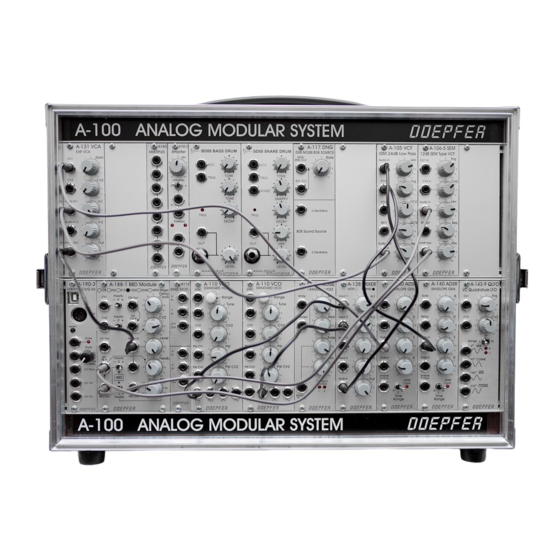
Page 9: Overall Design
2. Overall design 2.1 Introduction 3 HU The A-100 modular system is based on a standard 19” rack system A-100 G into which individual Modules can be fitted in any chosen layout. The rack system (see Fig. 1) conforms to the 19”... -
Page 10: Installing Modules
Important: you going ahead and installing them. Read on! Before you install a module into the rack D First of all, take the A-100’s plug out of the wall system: socket. D Calculate the total current requirement D Plug the supplied ribbon cable into the module’s... - Page 11 (see in Fig. 3). D Now plug the system A-100 back into the main Check very carefully that it is connected so power supply, and switch it on. that the coloured marking on the ribbon cable is at the bottom of the bus connector D Test out the newly installed module.
-
Page 12: Interconnecting Modules
2. Overall design System A - 100 doepfer A-118 A-110 A-120 VCF 1 A-130 VCA-LIN. NOISE / STANDARD VCO RANDOM LOW PASS FILTER In this case, double-check the connections, making SYNC White Range CV 1 CV 1 Blue completely sure that the ribbon cable is the right Freq. -
Page 13: Signal Flow In The A-100
System A - 100 3. A-100 signal flow doepfer 3. Signal flow in the A-100 Low Pass Filt er Input Output Output P it ch 3.1 The Principles of Voltage Control What makes analogue synthesizers (and modular sy- stems in particular) special is that the important para-... -
Page 14: Signals In The A-100
As well as modules which can be affected by voltage 3.2 Signals in the A-100 control, there are other modules like the ADSR and In the System A-100 there are three types of signal: LFO which themselves produce voltages to control other modules. -
Page 15: The System Bus In The A-100
It also carries the internal control system waveform shoots up from 0 V to +5V/12 V. The A-100 (INT.GATE and INT.CV), which some of the modules modules usually output +12V, but the corresponding (such as the VCO A-110, or ADSR A-140) can tap into. - Page 16 CV/gate leads, the A-100 BC. This is how you go about it: D Remove the A-100 from the electrical supply. D Remove Jumpers J1 and J2(see p.9) from the upper (see Fig. 8 !) and lower (see Fig. 8 ") ➀...
-
Page 17: Integrating The A-100 With Midi
3.4 Integrating the A-100 with MIDI VC Modules like the A-141 VC-ADSR and A-147 To link the A-100 into a MIDI system, you can use VC-LFO can be controlled via the A-190-1 or A-190-2, external MIDI interfaces like our MCV4, MSY2 or so that, for instance, a continuous MIDI controller can MCV24. - Page 18 3. A-100 signal flow 3. A-100 signal flow System A - 100 System A - 100 doepfer doepfer...
- Page 19 System A - 100 4. A-100 Basic System doepfer 4. A-100 Basic Systems Pos. Quantity Module Function A-110 It’s not in the nature of modular systems to have hard and fast rules about which modules should be inclu- A-114 Dual Ring Modulator ded.
-
Page 20: System A - 100 Doepfer
System A - 100 4. A-100 BS Basic system doepfer... -
Page 21: Accessories
System A - 100 5. Accessories doepfer Part Description A-100BUS Separate system bus One bus board with 14 connectors for connecting modules, 3 control LEDs (+12,-12,+5V) A-100AD5 5V Low cost adapter Additional power supply producing +5 V / 100 mA; can be connected to any free socket on the system bus board. - Page 22 Contains the schematics, silk screens, parts lists, assembly, test, basic principles and adjust- A-100SM ment instructions of all currently available modules. The words (e.g. assembly instructions) are in German language but schematics, components overlays and parts lists are international. Available only to A-100 customers. Subject to change without notice...
-
Page 23: Items Included As Standard
System A - 100 6. Standard items included doepfer 6. Items included as standard A-100G3/G6 - Rack System 3HU/6HU • Rack system, completely assembled, including The following parts are included in each order: two system bus boards, one 12V, 650mA power supply, internal power cables. - Page 24 6. Standard items included System A - 100 doepfer...
-
Page 25: Further Reading
Duke, Powell, Gleeson, DeFuria, Anderton, et al.) skill with which you can use modular systems like the A-100. Crombie, The Synthesizer & Electronic Keyboard Handbook ISBN 0 330 28681 1, and The New Com-... - Page 26 7. Further reading System A - 100 doepfer Specialist books in German Elrad, Heise-Verlag Hannover Electronic Musician, Polyphony Publishing Co., Dellmann / Thewes, Synthesizer-Handbuch, Musik Oklahoma City / USA Media / Augsburger Druck- und Verlagshaus, 1985 Electronics and Music Maker / Music Technology, Enders, Die Klangwelt des Musiksynthesizers, Cambridge, England.
-
Page 27: Module Overview
8. Module Overview System A-100 DOEPFER DOEPFER DOEPFER DOEPFER 8. Module Overview The following table may be used for planning and arranging an A-100 system regarding to need of space and current. (as of July 2009) Width Current Current@5V Module... -
Page 28: Vco
System A-100 8. Module Overview DOEPFER DOEPFER DOEPFER DOEPFER Module Width Curr. Curr.@5V Description 6/12/24/48 dB Low Pass / Band Pass A-108 voltage controlled low pass (ladder type) with 4 different slopes and bandpass Voltage Controlled Signal Processor A-109 combination of 24 dB low pass, VCA and panning unit (CEM3379 based) -
Page 29: Db Multimode Filter
8. Module Overview System A-100 DOEPFER DOEPFER DOEPFER DOEPFER Module Width Curr. Curr.@5V Description VCF 2 - 12 dB Multimode Filter A-121 voltage controlled 12 dB multimode filter (low pass, high pass, band pass, notch) VCF 3 - 24 dB Low Pass 2... -
Page 30: Vca (Lin)
System A-100 8. Module Overview DOEPFER DOEPFER DOEPFER DOEPFER Module Width Curr. Curr.@5V Description VCA - Voltage Controlled Amplifier A-130 voltage controlled amplifier with linear response VCA - Voltage Controlled Amplifier A-131 voltage controlled amplifier with exponential response Dual Low Cost VCA... - Page 31 8. Module Overview System A-100 DOEPFER DOEPFER DOEPFER DOEPFER Module Width Curr. Curr.@5V Description A-138 Mixer , mixer for audio or control voltages 10/20 a/b/c (a: linear or b: logarithmic controls or c: polarizing mixer) Manual Crossfader / Effect Insert Module...
-
Page 32: Lfo 1
System A-100 8. Module Overview DOEPFER DOEPFER DOEPFER DOEPFER Module Width Curr. Curr.@5V Description Morphing Controller A-144 control voltage modifier to obtain morphing effects in combination with A-135 LFO 1 A-145 modulation oscillator with 5 waveforms LFO 2 A-146 modulation oscillator with 2 waveforms and waveshape control... -
Page 33: Clock Divider
8. Module Overview System A-100 DOEPFER DOEPFER DOEPFER DOEPFER Module Width Curr. Curr.@5V Description Clock Divider A-160 frequency divider for clock/gate signals Clock Sequencer A-161 clock sequencer expansion for clock divider A-160 Dual Trigger Delay A-162 two independent trigger delay devices... - Page 34 System A-100 8. Module Overview DOEPFER DOEPFER DOEPFER DOEPFER Module Width Curr. Curr.@5V Description Dual Voltage Inverter A-175 two independent analog voltage inverter with displays CVS - Control Voltage Source A-176 3 manual adjustable control voltages External Foot Controller I...
- Page 35 8. Module Overview System A-100 DOEPFER DOEPFER DOEPFER DOEPFER Module Width Curr. Curr.@5V Description Gate / Trigger Combiner A-186 7 inputs that are "OR-wired" to the output, mainly for combination of gate/trigger signals Voltage Controlled DSP Effects Module (still under development)
- Page 36 3 display modes LCD Scope (available only as kit without the scope) A-197-2 kit to install a Velleman LCD scope into the A-100 system Trautonium / Ribbon-Controller A-198 Trautonium manual resp. ribbon controller, made of module + manual...
- Page 37 8. Module Overview System A-100 DOEPFER DOEPFER DOEPFER DOEPFER...
- Page 38 System A-100 8. Module Overview DOEPFER DOEPFER DOEPFER DOEPFER...
-
Page 39: Appendix
The 5V power supply needs to be mounted near to the main power input, on the blank upper back panel with Some A-100 modules, for instance the A-113, A-190 or four stand-offs, nuts, serrated washers, and bolts. A-191, need an extra 5 V power supply, as well as the Newer back panels (about since summer 1999) are standard one. - Page 40 9. Appendix System A - 100 doepfer t o t he (black ) blue connect ors of f rom m ains blue t he bus board inlet +5 V black (re d) black or brown black or brown black blue blue Fig.
-
Page 41: Installing The Ad5 Low-Cost 5V Adaptor
To install the AD5, do the following: • The current for the modules that require a 5V supply doesn’t exceed 100 mA (e.g. only one A-190 Isolate the A-100 rack from the mains power sup- or A-191) ply by removing the main plug. - Page 42 9. Appendix System A - 100 doepfer The fins of the heat sink should be facing to the right. It’s vital to make certain that the 16-way plug and socket marry exactly, and aren’t displaced up or down a pin, or to the left or right.
-
Page 43: Using The Mini Power Supply/Bus
A-100 manual, main introduction, chapter 3, ‘The 9.3. Using the mini power supply/ A-100 signal flow’.). The A-100 MNT is supplied as standard with an exter- 9.3.1. Introduction nal power supply, which has to be connected to the socket on the MNT’s circuit board. - Page 44 9. Appendix System A - 100 doepfer 9.3.2. A-100 MNT - Overview ➀ ➁ Controls: In- / Outputs: 1 LED : LED indicator for +12 V supply. ! BU 1 : Input for external power supply (7 ... 9 V AC) 2 LED : LED indicator for -12 V supply.
- Page 45 System A - 100 9. Appendix doepfer 9.3.3. Controls / indicators " ST 1 ... ST 4 The sockets labelled " on the diagram on p.2 are 1 LED • 2 LED where the modules are connected. LEDs 1 and 2 indicate that the power supply is working properly.
- Page 46 Connecting the ribbon cable to the bus board. D Now fix the module solidly in its case. D Re-connect the A-100 MNT’s power supply, and then switch on the mains again. D Test out the newly installed module. Fig. 1: Connecting the ribbon cable to the module If it doesn’t seem to be working as expected, imme-...
Need help?
Do you have a question about the A-100 and is the answer not in the manual?
Questions and answers