Advertisement
Quick Links
doepfer
Level
Audio
In
FCV 1
FCV 2
FCV 2
QCV
QCV
Audio
Out
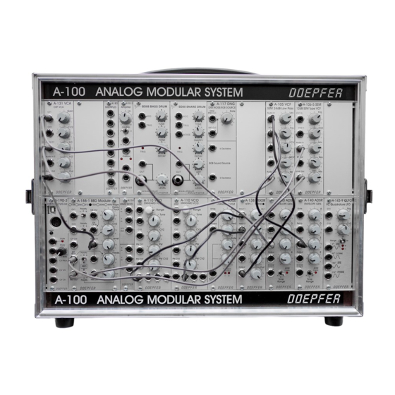
System A - 100
A-122
VCF 3
Frequency
Resonance
1. Introduction
The modules A-105 and A-122 are voltage-
controlled low-pass filters, which filter out the higher
parts of the sound spectrum, and lets lower frequen-
cies pass through.
The cut-off frequency determines the point at which
filtering takes effect. You can control this manually, or
by voltage control (filter modulation, for instance by
an LFO). Two CV inputs are available. The cut-off
slope is -24 dB/octave.
Voltage controlled resonance: for both A-105 and
A-122, resonance can be controlled not just manually,
but by voltages as well, right up to self-oscillation. In
this case, the filter behaves like a sine wave oscillator.
The A-105 is based on the special circuit SSM2044,
that was used in several devices of the companies
Korg (Polysix,
Mono-Poly),
(Prophets, Pro-One), PPG, Fairlight, Emu and Kawai.
The circuitry of the A-122 uses a chip of Curtis Elec-
tromusic (CEM), and is very similar to the classic
Oberheim filter sound. Because of the different cir-
cuits the A-105 and A-122 have considerably different
sounds and even sound different compared to the
other filters (e.g. A-120 Moog low pass, A-102 Diode
Low Pass or A-103 18dB low pass, A-124 Wasp filter).
As the functions and controls are the same for both
modules they are a combined in one manual.
A-105 / A-122
Sequential
Circuits
1
Advertisement

Related Manuals for DOEPFER A-100


Summary of Contents for DOEPFER A-100
- Page 1 System A - 100 A-105 / A-122 doepfer 1. Introduction The modules A-105 and A-122 are voltage- Level controlled low-pass filters, which filter out the higher A-122 Audio parts of the sound spectrum, and lets lower frequen- cies pass through.
- Page 2 A-105 / A-122 System A - 100 doepfer 2. VCF 3 - Overview Controls: 1 Lev. : Attenuator for audio input ! A-122 VCF 3 2 Frq. : Cut-off frequency control 24 dB Low Pass II 3 FCV : Attenuator for filter CV at input §...
- Page 3 System A - 100 A-105 / A-122 doepfer 3. Controls 1 Lev. Use this attenuator to control the amount of signal entering the filter input $. If the filter’s output sounds distorted, turn this control down, unless you deliberately want the sound as a special effect.
- Page 4 A-105 / A-122 System A - 100 doepfer At close to maximum resonance, the filter starts to 4. In / Outputs self-oscillate, and behaves like a sine wave oscilla- tor. Thanks to this effect, you can use the filter as an ! Audio In independent tone source.
-
Page 5: Audio Out
System A - 100 A-105 / A-122 doepfer 5. User examples $ QCV The filter’s cut-off frequency can be modulated in This socket is the voltage control input for the filter’s various ways: resonance. • VCF - LFO Modulation of the cut-off frequency produces cycli- If you patch a modulation source (eg LFO, ADSR) to cal changes of the sound spectrum. - Page 6 A-105 / A-122 System A - 100 doepfer A-121 multi-mode filter’s 12 dB) with voltage control- led resonance. To create a bandpass filter, put both modules in Freq. Freq. series (see Fig. 3). The band-width is governed by the A-122...
- Page 7 System A - 100 A-105 / A-122 doepfer Further examples can be found in the manual for the A-123 high pass filter.
- Page 8 A-105 / A-122 System A - 100 doepfer 6. Patch-Sheet The following diagrams of the module can help A-122 A-122 A-122 V CF 3 V CF 3 V CF 3 you recall your own Patches. They’re designed so 2 4 d B Low Pa s s I I...
Need help?
Do you have a question about the A-100 and is the answer not in the manual?
Questions and answers