Table of Contents
Advertisement
Quick Links
INSTRUCTION MANUAL
STEP-TOP ELECTRONIC ACTUATOR
(Linear type with Auto-setup function; Modbus communication)
BEFORE USE ....
Thank you for choosing M-System. Before use, please check
contents of the package you received as outlined below.
If you have any problems or questions with the product,
please contact M-System's Sales Office or representatives.
■ PACKAGE INCLUDES:
Step-Top Electronic Actuator unit......................................(1)
The Step-Top Electronic Actuator is not provided with a
yoke or other components required for mounting the unit to
a valve. They are to be provided by the user.
■ MODEL NO.
Confirm Model No. marking on the product to be exactly
what you ordered.
■ SAFETY PRECAUTIONS
Before use, please read all the following precautions
carefully to ensure the safety. These safety precautions,
classified into "WARNING" and "CAUTION" according to
the degree of damage that may be caused by improper use
of the product, are imperative to prevent an accident. Af-
ter reading, be sure to keep this manual always in a visible
and accessible place for the user.
WARNING Suggesting that failure to observe the pre-
cautions could result in death or serious personal injury.
CAUTION Suggesting that failure to observe the pre-
cautions could result in personal injury or damage to the
property.
WARNING
Remove power supply to the actuator before wiring to the
unit. It could cause electric shock.
Do not disassemble or modify the unit in any way.
It could cause electric shock, burn, or injury.
DO NOT step onto the actuator unit.
DO NOT rest a heavy object on or against the unit.
It could cause personal injury.
When installing the actuator unit outdoor or where it
is exposed to rain or water drops, adequate precautions
must be taken for preventing water from entering inside
through wiring conduits. It could cause electric shock.
CAUTION
DO NOT remove the cover of the actuator. It may cause
electric shock or injury.
The adjusters which are paint-sealed are for factory use
only and should be changed only by qualified M-System
personnel. Otherwise it could cause breakdown.
M-System is not liable for any malfunction or inconven-
ience caused by unauthorized changes made by the user.
SEN TRONIC
■ INSTRUCTION MANUAL
This manual describes necessary points of caution for han-
dling this product and specifically for installation, wiring,
hardware setting, and basic maintenance of the product.
This unit is factory-adjusted and calibrated according to the
Ordering Information Sheet.
When the user needs to change settings, please also refer to
the Section B of Operation Manual (EM-9255) for the Pro-
gramming Unit (Model: PU-2x).
POINTS OF CAUTION
■ POWER INPUT RATING & OPERATIONAL RANGE
• Locate the power input rating marked on the product and
confirm its operational range as indicated below:
24V DC: 24V rating ±10%, approx. 1 A
■ HUNTING
• Hunting is a condition in which the output stem is os-
cillated repeatedly and persistently without settling at a
single position.
• The actuator unit must operate at an average duty cycle
of 50% (approx. 13 strokes per minute) or less.
■ GENERAL PRECAUTIONS
• Remove the power supply to the actuator before wiring
the unit.
• DO NOT install signal wires and power supply wires to-
gether in one duct because it may cause a malfunction
due to induction noises. Alternatively, use shielded cables
for the input signal wires to prevent interference from
such noises.
• If input signals are to be turned on/off with power sup-
plied to the actuator, be sure to specify the output stem
operation for when abnormally low input is detected.
• DO NOT loosen the screws fixing the potentiometer in-
side the unit.
■ INSTALLATION
• Indoor, or outdoor where the unit is NOT exposed to di-
rect sunlight.
• Operating temperature -15 to +66°C (5 to 150.8°F)
• Operating humidity 30 to 90% RH (non-condensing)
• The unit is not designed to withstand all vibrations.
M-System does not guarantee long-term use of the unit
even with small vibrations. Please use the unit only after
evaluating in an actual installation environment. Par-
ticularly, avoid using under the condition where valve
cavitation or water hammer is likely to occur.
• Install the unit where it can be reached for maintenance
and inspection. Be sure to allow at least 20 cm (7.9 inch-
es) clearance above the unit and around the terminal box.
• Keep away from hazardous atmosphere such as explosive
or corrosive gases.
056 222 38 18
mailbox@sentronic.com
AG
MSP10
MODEL
EM-4887 P. 1 / 17
www.sentronic.com
Advertisement
Table of Contents

Subscribe to Our Youtube Channel
Related Manuals for M-system MSP10


Summary of Contents for M-system MSP10
- Page 1 This manual describes necessary points of caution for han- dling this product and specifically for installation, wiring, Thank you for choosing M-System. Before use, please check hardware setting, and basic maintenance of the product. contents of the package you received as outlined below.
- Page 2 MSP10 ■ PID CONTROL SIGNAL • Choose PID parameters carefully so that the MV remains as stable as possible to prevent hunting. Unstable control shortens the life of actuator and valve. ■ TRANSPARENT COVER FOR TERMINAL BOX • When reattaching the transparent cover after wiring, make sure that the packing and O ring are securely in place.
-
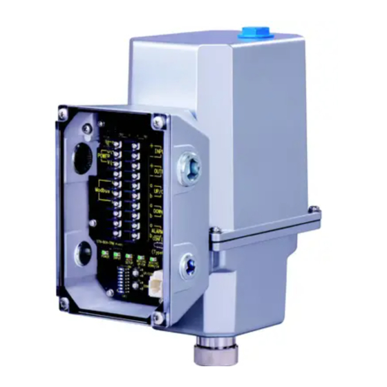
Page 3: Component Identification
MSP10 COMPONENT IDENTIFICATION Cover Terminal Box Packing Stepping Motor Transparent Cover Heater Terminal Block Wiring Conduits (4-G1/2) Packing Screw Nut Coil Output stem Figure 1. Component identification: MSP40/MSP50 + INPUT − U(+) + POWER OUTPUT V(−) − UP/CCW SIG. Modbus DOWN/CW SIG. - Page 4 MSP10 STATUS INDICATOR LED AND SIDE DIP SWITCH ■ STATUS INDICATOR LED COLOR STATUS FUNCTION POWER Green Power is ON. INPUT Green Position setpoint input (analog) of 0.37 V or greater is applied. (With 250 Ω receiving resistor for current input)
-
Page 5: Wiring Connection
MSP10 WIRING CONNECTION Remove the transparent cover for terminal box and wire to the terminal block according to the below figure. The unit can be operated once the power voltage and input signal are connected. Also wire retract/UP, extend/DOWN, alarm, and/or output signals, as necessary. - Page 6 MSP10 OUTPUT STEM STROKES Refer to the figure and the table below for the stroke range of the output stem according to the model. The upper-end position and the lower-end position can be set arbitrarily within the maximum stroke. Upper-end position Min.
- Page 7 MSP10 COMBINATION WITH VALVE ■ OPERATION DISTANCE WHEN COMBINED WITH VALVE When setting the upper-stop position and the lower-stop position, it is preferable that the operation distance becomes 80% or less with respect to the maximum stroke of the actuator.
- Page 8 MSP10 AUTO-SETUP MODE Auto-setup is the function for automatically detecting the valve seat surface on the lower-end side and/or the upper-end side and determining the lower-stop position and the upper-stop position of the actuator. Alternatively, by specifying the stroke length, the upper-stop or lower-stop position can be set to, for example, 13.00 mm up- ward/downward from the seated position.
- Page 9 MSP10 AUTO-SETUP TYPE STEPS OF AUTO-SETUP 3: Upper seal spring 1) The stem goes down toward the lower-end side by the specified stroke length. (Auto-setup is interrupted if the valve contacts the seat surface before reaching the specified Stroke specified stroke length.)
- Page 10 The PC configurator software helps the user to configure various parameters, execute Auto-setup, and to monitor operation status of the actuator. Download the STCFG from “Download” on the M-System’s web site http://www.m-system.co.jp Prepare the PC and the USB Type-C cable separately.
-
Page 11: Modbus Communication Specification
MSP10 MODBUS COMMUNICATION Modbus communication allows execution of Auto-setup and monitoring of the operation status of the actuator in the same manner as the programming unit (model: PU-2x) and the PC configurator software. Position set point can be input via Modbus instead of analog signal. - Page 12 Configurable, monitorable items by the PC configurator software. 1.2. Device information MODBUS PU-2x VALUE INITIAL ITEM SAVE CFG RANGE VALUE ADDRESS TYPE ITEM DISPLAY MSP10 unit ID 0x1141 – Model:x – ✓ Firmware: Major version 0 to 9 – Ver:x.y.z – ✓ Firmware: Minor version...
- Page 13 MSP10 MODBUS PU-2x VALUE INITIAL ITEM SAVE CFG RANGE VALUE ADDRESS TYPE ITEM DISPLAY Time ratio (%) of 70 - 80% position * 0.0 to 100.0 Pos70R:x – ✓ Time ratio (%) of 80 - 90% position * 0.0 to 100.0 Pos80R:x –...
- Page 14 MSP10 1.7. Modbus setting MODBUS PU-2x VALUE STANDARD ITEM SAVE CFG RANGE EX-FACTORY ADDRESS TYPE ITEM DISPLAY Input Select 0, 1 Inputsel:x ✓ ✓ 0: Analog input 1: Modbus input Node address 1 to 247 Addr:x ✓ ✓ Baud rate...
- Page 15 MSP10 OPERATION HARDWARE CODE SPEED AT DIVISION “[2] OPERATION TIME, THRUST, THRUST AT LOCK” SHIPMENT 1.9. Setting/executing Auto-setup MODBUS PU-2x VALUE STANDARD ITEM SAVE CFG RANGE EX-FACTORY ADDRESS TYPE ITEM DISPLAY Auto-setup type 0 to 4 ASType:x ✓ ✓ 0: Lower seal spring 1: Lower seal spring &...
-
Page 16: Operation Mode
MSP10 COMBINATION OF OPERATION MODE AND SPECIFICATIONS OPERATION MODE OPERATION SPECIFICATIONS SW1-5, 6 SW1-7 PU-2x Modbus Input Modbus Read data Manual Output stem Read data Setting Setting mode operation mode Retract (UP) / /Clear data operation operation Auto-setup /Clear data... -
Page 17: Maintenance
Screws Check that screws and bolts are securely fastened. Re-tighten them, if loose. For repair or parts replacement, contact M-System or our representatives. ■ LUBRICATION There is no need of oiling the Mini-Top electronic actuator in normal operating conditions. ■ REGULAR TEST RUNNING If the valve is not frequently operated, run a test operation regularly (once a week, for example) to ensure that the actuator operates normally.
Need help?
Do you have a question about the MSP10 and is the answer not in the manual?
Questions and answers