Advertisement
Quick Links
INSTRUCTION MANUAL
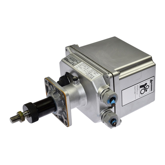
SERVO-TOP II ELECTRONIC ACTUATOR
BEFORE USE ....
Thank you for choosing M-System. Before use, please check
contents of the package you received as outlined below.
If you have any problems or questions with the product,
please contact M-System's Sales Office or representatives.
■ SAFETY PRECAUTIONS
Before use, please read all the following precautions care-
fully to ensure the safety. These safety precautions, classi-
fied into "WARNING" and "CAUTION" according to the de-
gree of damage that each item could cause, are imperative
to prevent an accident. After reading, be sure to keep this
manual always in a visible and accessible place for the user.
WARNING Suggesting that failure to observe the pre-
cautions could result in death or serious personal injury.
CAUTION Suggesting that failure to observe the pre-
cautions could result in personal injury or damage to the
property.
WARNING
Be sure to replace the terminal box cover which houses
the power input terminals on before turning on the power
supply. It could cause electric shock.
Power fuse: A glass tube power fuse (5.2 dia × 20 mm)
of the rating as shown below is incorporated for safety.
Be sure to remove the power supply before replacing it.
Replacing the fuse without turning off the power supply
could cause electric shock.
AC power: Medium time lag, M 3A 250V
DC power: Medium time lag, M 4A 125V
Remove power supply to the actuator before wiring to it.
It could cause electric shock.
DO NOT loosen the set screw fixing the lever of angle sen-
sor. Loosening it may cause a malfunction. It could cause
electric shock, burn, and injuries.
DO NOT step onto the actuator. DO NOT rest a heavy
object on or against it. It could cause injury.
When installing the PSN outdoor or where it is exposed
to rain or water drops, adequate precaution must be done
for preventing water from entering inside through wiring
conduits. It could cause electric shock.
DO NOT mount the PSN in such direction that the output
stem is at the top of the actuator. It could cause electric
shock.
Be surer that the power supply is removed. Hand or arm
could be caught and cause injury.
When the operation is completed, be sure to remove the
handle and cover the stem with a rubber cap. Hand or
arm could be caught and cause injury.
(linear type)
5-2-55, Minamitsumori, Nishinari-ku, Osaka 557-0063 JAPAN
Phone: +81(6)6659-8201 Fax: +81(6)6659-8510 E-mail: info@m-system.co.jp
MODEL
CAUTION
Inside the cover, the metal plate mounting printed wir-
ing boards located above the motor is also installed for
heat dissipation. The motor and the plate may become ex-
tremely hot during operation. DO NOT touch them with
bare hands. It could cause burn injury.
The adjustments which are paint locked are for factory
use only and should be changed only by qualified M-Sys-
tem personnel. M-System is not liable for any malfunc-
tion or inconvenience caused by unauthorized change of
them by the user. Otherwise it could cause breakdown.
■ PACKAGE INCLUDES:
SERVO-TOP II body ...........................................................(1)
Indicator (when the stem button is selected;
attached to the actuator body with a Scotch tape) ............(1)
Note: Yoke and other components necessary to attach the
PSN to a valve are to be provided by the customer.
■ MODEL NO.
Confirm Model No. marking on the product to be exactly
what you ordered.
■ INSTRUCTION MANUAL
This manual describes necessary points of caution when
you use this product, including installation and connection,
hardware setting, and basic maintenance procedures.
With the emergency shutdown option selected, please also
refer to PSN1/PSN3 Instruction Manual for this option
(EM-4857-A).
When you need to change software settings, please refer to
the Operation Manual for Model PU-2x (EM-9255), Section
B. This unit is factory adjusted and calibrated according to
the Ordering Information included in the product package.
If you do not need to change the pre-adjusted setting, you
can skip the sections on PU-2x programming in this manual
and the Operation Manual for Model PU-2x.
PSN1/PSN3
EM-4857 Rev.10 P. 1 / 9
Advertisement

Subscribe to Our Youtube Channel
Related Manuals for M-system PSN1


Summary of Contents for M-system PSN1
- Page 1 BEFORE USE ..Inside the cover, the metal plate mounting printed wir- Thank you for choosing M-System. Before use, please check ing boards located above the motor is also installed for contents of the package you received as outlined below.
- Page 2 • Inside building. If outside, keep away from direct sun- light. • Operating temperature -25 to +55°C (-13 to +131°F) for PSN1; -15 to +55°C (5 to 131°F) for PSN3. • Operating humidity 30 to 85% RH (non-condensing) • Vibration 2 G (19.6 m/s ) max.
- Page 3 PSN3-6x1 66 to 126 2.60 to 4.96 PSN3-6x2 52 to 112 2.05 to 4.41 Figure 2. Operational Range of the Output Stem EM-4857 Rev.10 P. 3 / 9 5-2-55, Minamitsumori, Nishinari-ku, Osaka 557-0063 JAPAN Phone: +81(6)6659-8201 Fax: +81(6)6659-8510 E-mail: info@m-system.co.jp...
- Page 4 4) Screw the valve stem into the output stem until there is little opening between them. Scale Plate For applying a sealing pressure, refer to flexure values in Table 3 (e.g. 1 mm for applying 1500 N for PSN1-x1) and Valve Stem Button screw it until the opening equals the value.
- Page 5 (Valve stem pushed in.) In DIRECT action, the input signal 0 – 100% corresponds to the position output signal 20 – 4mA DC. EM-4857 Rev.10 P. 5 / 9 5-2-55, Minamitsumori, Nishinari-ku, Osaka 557-0063 JAPAN Phone: +81(6)6659-8201 Fax: +81(6)6659-8510 E-mail: info@m-system.co.jp...
- Page 6 4) Indicating Current Setting Key in the ITEM No. that you want to check. (N = 0 to 9) Press [ITEM] [N] [N]. EM-4857 Rev.10 P. 6 / 9 5-2-55, Minamitsumori, Nishinari-ku, Osaka 557-0063 JAPAN Phone: +81(6)6659-8201 Fax: +81(6)6659-8510 E-mail: info@m-system.co.jp...
- Page 7 Speed 5000 Acceleration or deceleration is not included in the speed. Acceleration or deceleration respectively requires ap- 4000 prox. 0 to 2 sec.; takes longer with faster speed. Table 5. PSN1 opening/closing speed limit 3000 SPEED SPEED [V] OPERATION THRUST...
- Page 8 Re-tighten them. Check that the nut at the valve stem is not loose. Re-tighten it and calibrate. For repair or parts replacement, contact M-System or representatives. ■ LUBRICATION There is no need of oiling the PSN in normal operating conditions.
- Page 9 Wiring of the temperature sensor is broken Check the connector and leadwires. or the connector is detached. For repair or parts replacement, contact M-System or representatives. LIGHTNING SURGE PROTECTION M-System offers a series of lightning surge protectors for protection against induced lightning surges. Please contact M-System to choose appropriate models.
Need help?
Do you have a question about the PSN1 and is the answer not in the manual?
Questions and answers