Dahua DHI-ARC3008C User Manual
Alarm controller
Hide thumbs
Also See for DHI-ARC3008C:
- User manual (50 pages) ,
- Installer manual (111 pages) ,
- User manual (137 pages)
Table of Contents
Advertisement
Quick Links
Advertisement
Table of Contents

Related Manuals for Dahua DHI-ARC3008C


Summary of Contents for Dahua DHI-ARC3008C
- Page 1 Alarm Controller User’s Manual ZHEJIANG DAHUA VISION TECHNOLOGY CO., LTD. V2.0.0...
-
Page 2: Foreword
This manual introduces the installation, functions and operations of the alarm controller (hereinafter referred to as "controller"). Read carefully before using the device, and keep the manual safe for future reference. Models DHI-ARC3008C Safety Instructions The following signal words might appear in the manual. Signal Words... - Page 3 User’s Manual About the Manual ● The manual is for reference only. Slight differences might be found between the manual and the product. ● We are not liable for losses incurred due to operating the product in ways that are not in compliance with the manual.
-
Page 4: Important Safeguards And Warnings
User’s Manual Important Safeguards and Warnings This section introduces content covering the proper handling of the controller, hazard prevention, and prevention of property damage. Read carefully before using the controller, and comply with the guidelines when using it. Transportation Requirements ●... - Page 5 User’s Manual Installation Requirements ● Do not connect the power adapter to the controller while the adapter is powered on. ● Strictly comply with the local electric safety code and standards. Make sure the ambient voltage is stable and meets the power supply requirements of the controller. ●...
- Page 6 User’s Manual to the controller label. ● The controller is a class I electrical appliance. Make sure that the power supply of the controller is connected to a power socket with protective earthing ● The appliance coupler is a disconnection controller. Keep it at a convenient angle when using it. Before acting on a system component, or while you are installing or servicing the controller, make sure to disconnect both the primary (mains power) and secondary (battery) power supply of the system.
- Page 7 User’s Manual The ground connection must comply with the valid European standards. It is required that the ground conductor be connected between the casing and the door. ● External circuit breaker The power supply of the controller is not equipped with a circuit breaker. To ensure that controller installation meets the local standards, an external circuit breaker or a bipolar mains switch (16A curve C, opening stroke min.
- Page 8 User’s Manual ● Replace the batteries with the correct model and dispose of the unwanted ones as instructed to avoid failing to meet the requirements of the safeguards. Some types of lithium batteries are not acceptable. ● The most important controls: ◇...
-
Page 9: Table Of Contents
User’s Manual Table of Contents Foreword ........................................I Important Safeguards and Warnings ............................III 1 Introduction ......................................1 1.1 Overview ......................................1 1.2 Features ......................................1 1.3 Technical Specifications ................................. 2 2 Keypad ........................................7 2.1 Dimensions ....................................7 2.2 Installation ....................................7 2.3 Wiring ...................................... - Page 10 User’s Manual 5.1.8 Arming from Remote ..............................28 5.2 Disarming ....................................28 5.2.1 Total Disarming from the Keypad ........................28 5.2.2 Total Disarming with the Timer ..........................28 5.2.3 Total Disarming through Telephone or SMS ....................29 5.2.4 Disarming under Duress ............................29 6 User Menu ......................................
-
Page 11: Introduction
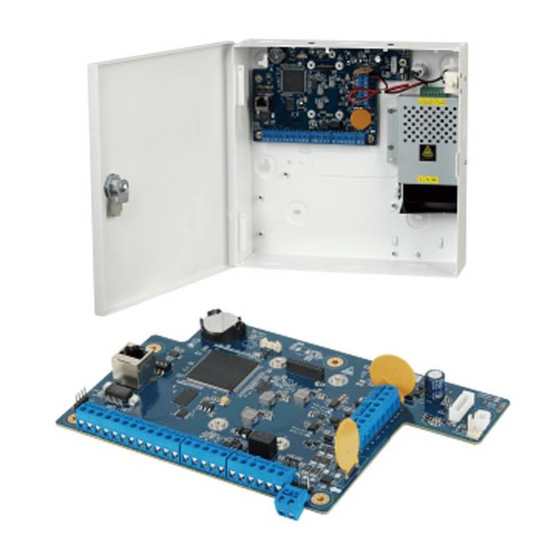
User’s Manual 1 Introduction 1.1 Overview The alarm controller is a high performance anti-theft controller designed for the middle and small alarm solution application. Adopting embedded Linux operation system and relying on embedded platform, the system can run steadily with advanced controlling technology and strong data transmission ability. -
Page 12: Technical Specifications
User’s Manual ● With GSM/GPRS/LTE network ports for events SMS reporting and remote control, events vocal message reporting by dialing and remote control, and mobile phone app connection ability when Ethernet connection is failed. ● With 10/100M self-adaptive Ethernet port. ●... - Page 13 User’s Manual Type Parameter Description Configuration Method Keypad and client software Keyboard, swipe card, DMSS app, SMS, DSS Arm and Disarm Method Professional, and VTH Supports customized access to the third parties External Agreement by SIA Number of Keypads Max. 8 keypads Area 8 areas Partition...
- Page 14 User’s Manual Type Parameter Description Max. Output Voltage 2.76 A@14.5 VDC Max. Current Available 2.76 A Max. Ripple Max. 30 mV Power Consumption Max. 40 W Max. Output Voltage 12 V; 1A Mains fuse (non - RT21: 5 A replaceable) Battery Capacity 1 x 12 V/7.2 Ah Battery Flame Class...
- Page 15 User’s Manual Type Parameter Description Net Weight (without ≤3 kg battery) Outer diameter: 5.5 mm Inner diameter: 2.9 mm Expansion Bolts Length: 24.5 mm Quantity: 4 Diameter: 4 mm Self-tapping Screw Length: 25 mm Quantity: 4 ACE Classification Type A CE: 4789104635 EN 50131-3, EN 50131-6, EN 50136-2 Certifications...
- Page 16 User’s Manual Communication Devices Reporting Communication Protocols Category Time Device to be Used PSTN 2G/3G — The two check marked 90 s Encrypted √ √ communication devices ATE: Alarm transmission equipment. SPx (Single Path): A value that indicates the performance level achieved by a single communication device, according to the EN 50136–1 standard.
-
Page 17: Keypad
User’s Manual 2 Keypad This chapter introduces the dimensions, main functions, indicators, keys operations, and installation of the keypad. 2.1 Dimensions Figure 2-1 Dimensions (unit: mm [inch]) 2.2 Installation Prerequisites Make sure to prepare following expansion bolts and self-tapping screws first. ●... - Page 18 User’s Manual Figure 2-2 Install the controller...
-
Page 19: Wiring
User’s Manual 2.3 Wiring Figure 2-3 keypad connection... -
Page 20: Structure
User’s Manual 2.4 Structure Figure 2-4 Structure Table 2-1 Function Name Function Displays all the system information including management LCD display and programming. For details, see "2.7 LCD Display". Displays information about power status, battery status, LED indicators failures, bypass, and alarm status of each area. For details, see "2.6 LED Indicators". -
Page 21: Numeric Keys (From 0-9)
User’s Manual Figure 2-5 Keys 2.5.1 Numeric Keys (from 0-9) The numeric keys have following functions. ● Enter access codes as required to access programming (technician or user) or to arm/disarm. ● The keys from 1 to 8 represent eight areas. When the zone is not ready, you can press and hold the key to show the NOT READY details, and when the key LED light slowly flashes or quickly flashes, press and hold the key to show the alarm details. -
Page 22: Key Combination Operations
User’s Manual Function ● Move the pointer to the left when you edit. ● Press and hold to delete the text. ● Bypass the zones as follows. 1. Enter the access code. 2. Press , and then the screen of setting the bypass zones is displayed. - Page 23 User’s Manual Table 2-3 Key combination operations Function ● On the main screen, press + 0 (F0) to view the GSM connection status, which is shown with eight bars. ● Press + 0 (F0) again to return to the main screen. + 0 (F0) The system automatically returns to the main screen within 2 minutes if no operations are performed.
-
Page 24: Led Indicators
User’s Manual 2.6 LED Indicators There are 12 LED indicators on the keypad that respectively shows information about power status, battery status, faults, bypass, and alarm status of each area. 2.6.1 Overview Table 2-4 LED indicators Icon Color Meaning Green Power status. -
Page 25: Lcd Display
User’s Manual There are eight LED indicators located below the LCD display representing the status of the areas. From left to right, there is the alarm status of area 1 to area 8. Figure 2-6 Area status LED indicators ● Glows red: The area is armed. ●... - Page 26 User’s Manual Symbol Meaning Level of GSM signal. Each is equivalent to one bar, and maximum eight bars. Symbols on the Second Line of Display Table 2-6 Symbols on the second line of display Symbol Event Upper case T Total arming. Partition arming 1.
-
Page 27: Expansion Module (Optional)
User’s Manual 3 Expansion Module (Optional) The expansion module is not provided, and you need to purchase it as needed. 3.1 Dimensions Figure 3-1 Dimensions (unit: mm [inch]) 3.2 Wiring Figure 3-2 Wiring of detectors... -
Page 28: Module Functions
User’s Manual Figure 3-3 Expansion module connections 3.3 Module Functions Dip switch addresses of the expansion modules (including alarm input and output modules) are from 1 to 8. - Page 29 User’s Manual Alarm Input Module 8 alarm inputs and 2 alarm outputs are supported with alarm input modules. The alarm input module with Dip switch address 1 receives alarm input signals from wired zones of 9–16, and connects to alarm output devices of 3–4. Other alarm input modules are connected by analogy till the module addressed 8, which receives alarm input signals from wired zones of 65–72, and connects to alarm output devices of 17–18.
-
Page 30: Module (Optional)
User’s Manual 4 4G Module (Optional) The 4G module is not provided, and you need to purchase it as needed. 4.1 Dimensions Figure 4-1 Dimensions (unit: mm[inch]) 4.2 Installing 4G Modules Step 1 Remove two plugs on the controller. - Page 31 User’s Manual Figure 4-2 Remove plugs Step 2 Attach the thermal pad to the 4G module. Figure 4-3 Install the thermal pad Step 3 Attach one end of the antenna patch cord to the main port of the 4G module. Step 4 Secure the 4G module to the controller with screws.
- Page 32 User’s Manual Figure 4-4 Secure the 4G module Step 5 Secure the other end of the antenna patch cord to the antenna hole, and then install the external antenna on the hole. Figure 4-5 Secure the antenna patch cord Step 6 Connect the 4G module to the 4G port on the main board with the provided wire.
-
Page 33: Arming And Disarming
User’s Manual 5 Arming and Disarming 5.1 Arming When you arm the system, the detectors that are connected to it are activated. If an alarm event occurs, the detectors will trigger an alarm. When any of the scenarios listed below occur, the system cannot be armed. The keypad will display which zone or area is abnormal, and will give you the option to continue arming. -
Page 34: Total Arming
User’s Manual 5.1.1 Total Arming Total arming activates protection for the entire alarm system and is used when there are no persons on the premise. Step 1 Confirm that all zones are ready to be armed, which means that an * must not be placed in place of the dash in the second line of the LCD display. -
Page 35: Partition 2 Arming
User’s Manual go to the ZONE MANAGER menu to set bypass for these zones. Step 2 Enter your user code, and then press The numbers of areas that are ready to be armed are shown on the second line of the LCD display. -
Page 36: Partition 1+2 Arming
User’s Manual The numbers of areas ready for arming are shown on the second line of the LCD display. Step 3 Select the areas that need to be involved in the arming by pressing the corresponding numeric key (from 1 to 8). Step 4 Press to do the arming. -
Page 37: Forced Arming
User’s Manual Figure 5-7 Mixed arming 5.1.5 Forced Arming Forced arming allows you to override when the system is not ready to be armed because of open zones, without any additional operations. This type of arming can be useful when zones, such a windows or door, are open or not ready to be armed, and you know their status ad wish to leave them open. -
Page 38: Arming Through Timer
User’s Manual You can also arm the system with IMMEDIATE or DELAYED exit time for rapid arming if this is programmed by the technician. Step 2 (Optional) To disarm from rapid arming, you need to type in a valid user code. 5.1.7 Arming through Timer You can arm the alarm system by timer that is set on the SYSTEM TIMER menu. -
Page 39: Total Disarming Through Telephone Or Sms
User’s Manual 5.2.3 Total Disarming through Telephone or SMS The alarm system can also be disarmed from your phone through a specific procedure with an interactive vocal guide or through SMS text messages. 5.2.4 Disarming under Duress You can perform disarming through a changed user code or a specific duress code to trigger a duress alarm. -
Page 40: User Menu
User’s Manual 6 User Menu This chapter describes the operations included in the user menu. The user menu consists of many menus for management and programming operations. They are as below: ● ZONE TROUBLES ● SYSTEM TROUBLES ● ZONES MANAGER ●... - Page 41 User’s Manual Figure 6-1 Zone troubles Step 2 Press to enter the menu. ● If there are no fault zones, the screen shows NO TROUBLE. ● If there are zones in trouble, then any of these 3 categories will appear: TAMPER, SHORT, and MASK.
-
Page 42: System Troubles
User’s Manual Figure 6-3 Filter by activation status Step 4 Press to confirm the setting, and then press to return to the ZONE TROUBLES menu. Then you can press to move to the next menu or press to exit from the user menu. -
Page 43: Zone Manager
User’s Manual Option Description ● System date and time ● 220 VAC main supply ● Low battery ● Battery trouble ● PSTN line TROUBLE ● GSM line ● Antenna fault ● SIM expiration ● PWD default COM TROUBLE Device fault (such as keypad and module) Step 3 Press to confirm the setting, and then press... -
Page 44: Logbook Event
User’s Manual Step 5 Press to confirm the setting, and then press to return to the wired zones selection menu. Then you can continue with programming other wired zones, or press to return to the ZONE MANAGER menu from where you can press to move to the next menu or press to exit from the user menu. -
Page 45: Chime Zones
User’s Manual 6.5 Chime Zones The CHIME ZONES menu is useful for obtaining a keypad buzzer sound whenever a specific zone is affected while the system is disarmed. This function is particularly useful for monitoring the presence of persons in particular zones or the opening of a door or window. The CHIME ZONES menu activates chime mode for an individual zone. -
Page 46: Configuring Authority Level
User’s Manual User type Authority level Only has control over operations assigned to the master. The master can only Master change his own code and those of a lower level and access the user menu up to option 9. Only has control over operations assigned to the user. The user can only User change his own code and access the user Menu up to option 8. - Page 47 User’s Manual Table 6-4 Access code level and submenus Submenu Setting Set the code to an operating or non-operating status. ● ACTIVE STATUS ● ISOLATE LEVEL Give an authority level to the user. AREAS Establish which areas the access code can be used for. PART1 Establish whether the access code can operate partition 1 and partition 2 arming types under the selected areas.
-
Page 48: Configuring Access Code
User’s Manual Submenu Setting Establish whether the access code can grant access to control the controller through a phone call or SMS. REMOTE ● YES ● NO Establish whether the access code is limited to operation only during certain time periods. There are 4 timers that can be set for the access code, and each timer TIMER can select from eight timers that are configured in the system. -
Page 49: Deleting An Access Code
User’s Manual 6.6.3.2 Deleting an Access Code Access code 1 cannot be deleted. On the ACCESS CODE submenu, for example, access code 2, press and hold Step 1 for at least three seconds. The NO PRESENT message is shown to indicate that the access code was deleted. Step 2 Press to exit. -
Page 50: Firmware Version
User’s Manual Figure 6-8 Technician menu Step 3 Press 3 beeps confirms that the technician code is operational, authorizing it for a set period of time. Step 4 Press to move to the next menu or press to exit from the user menu. 6.8 Firmware Version The FIREWARE VERSION examines the version of software installed in the controller and the keypad. -
Page 51: System Timers
User’s Manual ● When the system is in the armed status, entering WALK TEST menu prompts the unauthorized message. ● When one Keypad has entered the walk test mode, other keypads shows OUT OF USE. ● The WALK TEST menu cannot return to the main screen automatically. Step 1 Enter the access code, and then press The ZONE TROUBLE menu is shown on the LCD display. - Page 52 User’s Manual Figure 6-12 System timer Step 3 Press to enter the submenu from where you can select a desired timer that you want to set (8 timers in total). By pressing + 2 (F2), you can enter EDITING mode to change the description of timer. Step 4 Press to select a timer, and then press...
-
Page 53: Date And Time
User’s Manual Submenu Setting Establish whether the timer being programmed. ● YES: The timer is blocked during the holiday periods. For example, if associated with the arming/disarming of areas, it no longer causes disarming during the holiday period. If associated with a code, HOLIDAYS remote controls or outputs, these will no longer be operative during the holiday period. -
Page 54: Holiday
User’s Manual can also press to change the value, and press to move to the next editing. Table 6-6 Date and time settings Submenu Setting TIME Set the time for the controller. DATE Set the date for the controller (day/month/year). DST ENABLE Enable the DST function. -
Page 55: Telephone Number
User’s Manual By pressing + 2 (F2), you can enter EDITING mode to change the description of the holiday. Step 4 Press to select a holiday, and then press to enter programming mode Figure 6-15 Holiday programming ● 1: Holiday start day ●... - Page 56 User’s Manual Figure 6-16 Telephone number Step 3 Press to enter the screen from where you can select the submenus from TEL NUM, SMS NUM, and SIM NUM by pressing Step 4 Configure the phone number submenu settings. ● TEL NUM 1.
-
Page 57: Remote Service
User’s Manual Submenu Setting Press 1 to 8 to select the alarm event from which areas can be sent to this AREA SMS number. Press 1 to 5 to select which event can be sent to this SMS number. ● 1: S-system event ●... -
Page 58: Security Code
User’s Manual Step 4 On the STATE submenu, select YES and NO. ● YES: Allows remote control by the Installer from telephone call, SMS, app, or platform. ● NO: Do not allow remote control by the Installer. Step 5 Press to return to the REMOTE SERVICE menu. -
Page 59: Rfid Cards
User’s Manual 6.16 RFID Cards After adding Radio Frequency Identification (RFID) cards, you can use them to arm and disarm your areas by using a combination of card or card swiping with a password. Step 1 Enter the access code, and then press The ZONE TROUBLE menu is shown on the LCD display. - Page 60 User’s Manual Submenu Descriptions AREAS Set one or multiple areas where the RFID card can be used. Set the arming status. ● IMMEDIATE The area is immediately armed. ARMING ● DELAYED The area is armed after the exit delay time, which can be set by the installer.
-
Page 61: Appendix 1 Keypad Buzzer Sound
User’s Manual Appendix 1 Keypad Buzzer Sound Appendix Table 1-1 Keypad sound Buzzer sound Description One slight beep Keypad pressing. One beep Menu entering. ● Switching between the first menu and the last menu Continuous three beeps after log in to the system. ●... -
Page 62: Appendix 2 Event Log Messages
User’s Manual Appendix 2 Event Log Messages Appendix Table 2-1 Event log messages — — Event message Description Event message Description AL.SF Siren Fault P1.Arm Partitial1 Arm Alarm P2.Arm Partitial2 Arm S.T.RES Siren Tamper Restore AL.PAN. Panic Alarm AL.S.T Siren Tamper Alarm AL.ROB. - Page 63 User’s Manual Event message Description Event message Description System Battery Low SYS.BAT.Low.VOL. WLI.M.T Voltage Wireless Input Module Tamper System Battery SYS.BAT. Restore WL.IN.MODU.TAM Restore Wireless Input SYS. System WL IN.Module Module RES. Restore — When the following faults occur at the same time, the priority is as follows: A>B>C>D>E. In the same level, the subsequent time will be reported first.
-
Page 64: Appendix 3 Cybersecurity Recommendations
IP video surveillance is not immune to cyber risks, but taking basic steps toward protecting and strengthening networks and networked appliances will make them less susceptible to attacks. Below are some tips and recommendations from Dahua on how to create a more secured security system. - Page 65 User’s Manual 1024–65535, reducing the risk of outsiders being able to guess which ports you are using. 6. Enable HTTPS We suggest you to enable HTTPS, so that you visit Web service through a secure communication channel. 7. MAC Address Binding We recommend you to bind the IP and MAC address of the gateway to the device, thus reducing the risk of ARP spoofing.
- Page 66 User’s Manual device. More information Please visit Dahua official website security emergency response center for security announcements and the latest security recommendations.
- Page 67 User’s Manual...
Need help?
Do you have a question about the DHI-ARC3008C and is the answer not in the manual?
Questions and answers