Table of Contents
Advertisement
Advertisement
Table of Contents

Related Manuals for Dahua DHI-ASC1204B


Summary of Contents for Dahua DHI-ASC1204B
- Page 1 Four-door One-way Access Controller User’s Manual V1.0.0...
-
Page 2: Cybersecurity Recommendations
Cybersecurity Recommendations Mandatory actions to be taken towards cybersecurity 1. Change Passwords and Use Strong Passwords: The number one reason systems get “hacked” is due to having weak or default passwords. It is recommended to change default passwords immediately and choose a strong password whenever possible. - Page 3 ● Only forward the HTTP and TCP ports that you need to use. Do not forward a huge range of numbers to the device. Do not DMZ the device's IP address. ● You do not need to forward any ports for individual cameras if they are all connected to a recorder on site;...
- Page 4 Ideally, you want to prevent any unauthorized physical access to your system. The best way to achieve this is to install the recorder in a lockbox, locking server rack, or in a room that is behind a lock and key. 15.
-
Page 5: Regulatory Information
Regulatory Information FCC Information CAUTION Changes or modifications not expressly approved by the party responsible for compliance could void the user's authority to operate the equipment. FCC conditions: This device complies with part 15 of the FCC Rules. Operation is subject to the following two conditions: This device may not cause harmful interference. -
Page 6: Foreword
Foreword General This document elaborates on structure, installation and wiring of four-door one-way access controller. Safety Instructions The following categorized signal words with defined meaning might appear in the Manual. Signal Words Meaning Indicates a high potential hazard which, if not avoided, will result in death or serious injury. - Page 7 All the designs and software are subject to change without prior written notice. The product updates might cause some differences between the actual product and the Manual. Please contact the customer service for the latest program and supplementary documentation. ...
-
Page 8: Important Safeguards And Warnings
Important Safeguards and Warnings The following description is the correct application method of the device. Please read the manual carefully before use, in order to prevent danger and property loss. Strictly conform to the manual during application and keep it properly after reading. Operating Requirement ... -
Page 9: Table Of Contents
Table of Contents Cybersecurity Recommendations ......................I Regulatory Information ........................IV Foreword ..............................V Important Safeguards and Warnings ....................VII 1 Overview .............................. 1 1.1 Functional Feature ........................1 1.2 External Dimension ........................1 2 Installation Guide ..........................3 2.1 System Structure ........................... 3 2.2 Device Installation ......................... - Page 10 5 Technical Parameters ........................26 Table of Contents IX...
-
Page 11: Overview
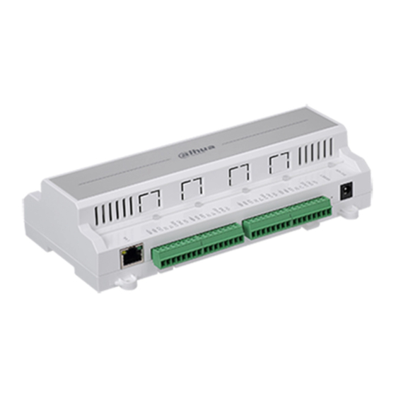
Overview Four-door one-way access controller is a controlling device which compensates video surveillance and visual intercom. It has neat and modern design with strong functionality, suitable for commercial building, corporation property and intelligent community. 1.1 Functional Feature Its rich functions are as follows: ... - Page 12 Figure 1-2 Overview 2...
-
Page 13: Installation Guide
Installation Guide 2.1 System Structure System structure of four-door one-way access controller, door lock and reader is shown in Figure 2-1. Figure 2-1 2.2 Device Installation There are two installation modes. Mode 1: fix the whole device onto the wall with screws. ... -
Page 14: Disassembly
Figure 2-2 Mode 2 Installation diagram is shown in Figure 2-3. Figure 2-3 Step 1 Fix the U-shaped guide rail onto the wall with screws. Step 2 Buckle the upper rear part of the device into upper groove of the U-shaped guide rail. Step 3 Push the snap joint at the bottom of the device upwards. -
Page 15: Wiring Diagram
Figure 2-4 2.4 Wiring Diagram 2.4.1 Wiring Description of Access Controller This device supports four-door in or out. In case of alarm input, trigger external alarm output device to give an alarm. Device wiring diagram is shown in Figure 2-5. Figure 2-5 Interfaces are described in Table 2-1. -
Page 16: Wiring Description Of Exit Button/Door Contact
Indicator lights are described in Table 2-2. Table 2-2 Description Lock status indicator Power indicator 2.4.2 Wiring Description of Exit Button/Door Contact Corresponding wiring terminals of exit button and door contact are shown in Figure 2-6. Please refer to Table 2-3 for descriptions of wiring terminals. Figure 2-6 Table 2-3 Port... - Page 17 Port Wiring Terminal Description PUSH3 Exit button of door 3 Shared by exit button of door 3 and door contact input of door 3 Door contact input of door 3 PUSH4 Exit button of door 4 Shared by exit button of door 4 and door contact input of door 4 Door contact input of door 4 2.4.3 Wiring Description of Lock...
- Page 18 Figure 2-9 Table 2-4 Port Wiring Terminal Description COM1 Lock control of door 1 COM2 Lock control of door 2 Lock control output port COM3 Lock control of door 3 COM4 Lock control of door 4 2.4.4 Wiring Description of Reader 1 door only supports to connect one type of reader—485 or Wiegand.
-
Page 19: Wiring Description Of External Alarm Input
Table 2-6 Reader Type Connection Mode Length 485 Reader CAT5e network cable, 485 connection 100m Wiegand Reader CAT5e network cable, Wiegand connection 100m 2.4.5 Wiring Description of External Alarm Input External alarm input connection is shown in Figure 2-10. Please refer to Table 2-7 for descriptions of wiring terminals. - Page 20 Figure 2-12 Table 2-8 Port Wiring Terminal Description OUT1+ ALM-IN triggers alarm output. Internal external Door timeout alarm output ports are Alarm output intrusion alarm output. able to connect audible OUT1- Tamper alarm output of and visual sirens. ...
-
Page 21: Dip Switch
Alarm Alarm Event Alarm Signal Alarm Signal Alarm Status Type Input Port Output Port door reader Tamper alarm of no. 3 RS-485/CASE door reader Tamper alarm of no. 4 RS-485/CASE door reader 2.5 DIP Switch Operate with DIP switch. Figure 2-13 ... -
Page 22: Smart Pss Config
Smart PSS Config Access controller is managed with Smart PSS client, so as to realize control and right configuration of one door and door groups. This chapter mainly introduces quick configuration. For specific operations, please refer to User’s Manual of Smart PSS Client. Smart PSS client offers different ports for different versions. - Page 23 Figure 3-2 Step 2 Input device segment and click “Search”. The system displays search results. Click “Refresh” to update device information. Select a device, click “Modify IP” to modify IP address of the device. For specific operations, please refer to User’s Manual of Smart PSS Client. Step 3 Select the device that needs to be added, and click “Add”.
-
Page 24: Manual Add
After completing adding, the system continues to stay at “Auto Search” interface. You can continue to add more devices, or click “Cancel” to exit “Auto Search” interface. After completing adding, Smart PSS logs in the device automatically. In case of successful login, online status displays “Online”. - Page 25 Figure 3-6 Step 2 Set device parameters. For specific parameter descriptions, please refer to Table 3-2. Table 3-2 Parameter Description It is suggested that device should be named by the Device Name monitoring zone, so as to facilitate maintenance. Select “IP/Domain Name”. Add devices according to Method to add device IP address or domain name.
-
Page 26: Add User
Figure 3-7 3.3 Add User Add users and bind with cards, so as to distribute authority. In “New” interface, click “Access” to enter “Access” interface, and complete access config here. Smart PSS Config 16... -
Page 27: Card Type
Figure 3-8 3.3.1 Card Type Card type shall be the same with card issuer; otherwise, it fails to read card number. In “Access” interface, click and then click to set the card type, as shown in Figure 3-9 and Figure 3-10. Smart PSS Config 17... -
Page 28: Single Add
Figure 3-9 Figure 3-10 3.3.2 Single Add Add a single user, send a card and input user info. Step 1 In “Access” interface, click , and then click , as shown in Figure 3-11. The system pops up “Add User” dialog box, as shown in Figure 3-12. Smart PSS Config 18... - Page 29 Figure 3-11 Figure 3-12 Step 2 Add user info manually, including basic info, fingerprint info and details. Please refer to Table 3-3 for details. Smart PSS Config 19...
-
Page 30: Add Door Group
Table 3-3 Parameter Description User ID (mandatory). Name (mandatory). Department (auto association). Card No.: input by card reader or input manually. Card type: general card, VIP card, guest card, patrol card, blacklist card and duress card. ... - Page 31 Figure 3-13 Step 2 Click “Add”. The system pops up “Add Door Group” dialog box, as shown in Figure 3-14. Figure 3-14 Smart PSS Config 21...
-
Page 32: Authorize
Step 3 Enter “Name”; select “Time Zone” and doors to be managed. Step 4 Click “OK” to complete adding. 3.5 Authorize Grant users authorities according to door group and user. 3.5.1 Authorize According to Door Group Select a door group, add corresponding users to the group, so all users in the group obtain authority of all doors in the group. -
Page 33: Authorize According To User
Figure 3-16 Step 4 In the search list, select the user and add to user list. Step 5 Click “OK” to finish authorization. The search list filters user info without card number. In the user list, cancel the added user and delete the user’s authority. 3.5.2 Authorize According to User Select a user, distribute door group and grant door group authority to the user. - Page 34 Figure 3-17 Step 2 Click The system pops up “Select Door Group” dialog box, as shown in Figure 3-18. Figure 3-18 Step 3 Select the door group and click “OK” to finish authorization. Smart PSS Config 24...
-
Page 35: Faq
For problems not included hereinafter, please contact local customer service personnel or consult headquarter customer service personnel. We will be always at your service. 1. Question: After power on, power indicator doesn’t turn on or the buzzer doesn’t respond. Answer: Please check whether power plug is inserted in place. Please pull it out and insert it again. - Page 36 Technical Parameters Parameter Specification Processor 32-bit ARM processor 12V 0.5A, and working temperature shall be External power supply 5℃~55℃. Memory capacity Max. number of user 100,000 Max. storage record 150,000 Communication port of reader Wiegand, RS485 Communication port of platform TCP/IP Number of connected reader 4 groups...
Need help?
Do you have a question about the DHI-ASC1204B and is the answer not in the manual?
Questions and answers