Dahua DHI-ARC3008C User Manual
Alarm controller
Hide thumbs
Also See for DHI-ARC3008C:
- User manual (50 pages) ,
- Installer manual (111 pages) ,
- User manual (67 pages)
Table of Contents
Advertisement
Quick Links
Advertisement
Table of Contents

Related Manuals for Dahua DHI-ARC3008C


Summary of Contents for Dahua DHI-ARC3008C
- Page 1 Alarm Controller User’s Manual ZHEJIANG DAHUA VISION TECHNOLOGY CO., LTD. V2.0.1...
-
Page 2: Foreword
This manual introduces the installation, functions and operations of the alarm controller (hereinafter referred to as "controller"). Read carefully before using the device, and keep the manual safe for future reference. Models DHI-ARC3008C Safety Instructions The following signal words might appear in the manual. Signal Words... - Page 3 User’s Manual fingerprints, and license plate number. You need to be in compliance with your local privacy protection laws and regulations to protect the legitimate rights and interests of other people by implementing measures which include but are not limited: Providing clear and visible identification to inform people of the existence of the surveillance area and provide required contact information.
-
Page 4: Important Safeguards And Warnings
User’s Manual Important Safeguards and Warnings This section introduces content covering the proper handling of the controller, hazard prevention, and prevention of property damage. Read carefully before using the controller, and comply with the guidelines when using it. Transportation Requirements ●... - Page 5 User’s Manual Installation Requirements ● Do not connect the power adapter to the controller while the adapter is powered on. ● Strictly comply with the local electric safety code and standards. Make sure the ambient voltage is stable and meets the power supply requirements of the controller. ●...
- Page 6 User’s Manual to the controller label. ● The controller is a class I electrical appliance. Make sure that the power supply of the controller is connected to a power socket with protective earthing ● The appliance coupler is a disconnection controller. Keep it at a convenient angle when using it. Electrical Safety Before acting on a system component, or while you are installing or servicing the controller, make sure to disconnect both the primary (mains power) and secondary (battery) power supply of the...
- Page 7 User’s Manual ● Ground connection The ground connection must comply with the valid European standards. It is required that the ground conductor be connected between the casing and the door. ● External circuit breaker The power supply of the controller is not equipped with a circuit breaker. To ensure that controller installation meets the local standards, an external circuit breaker or a bipolar mains switch (16A curve C, opening stroke min.
- Page 8 User’s Manual acceptable. ● The most important controls: ◇ The status of the power supplies and batteries. ◇ The status of the batteries and self-powered devices (sirens and transmitters). ◇ The functional efficiency and coverage of the movement and perimeter detectors. ◇...
-
Page 9: Table Of Contents
User’s Manual Table of Contents Foreword ........................................I Important Safeguards and Warnings ............................III 1 Introduction ......................................1 1.1 Overview ......................................1 1.2 Features ......................................1 1.3 Technical Specifications ................................. 2 2 Wiring and Installation ..................................8 2.1 Dimensions ....................................8 2.2 Installation .................................... - Page 10 User’s Manual 4.7 LCD Display ....................................26 5 Expansion Module (Optional) ..............................29 5.1 Dimensions ....................................29 5.2 Wiring ......................................30 5.3 Module Functions ..................................31 6 4G Module (Optional) ..................................33 6.1 Dimensions ....................................33 6.2 Installing 4G Modules ................................33 7 Installer Operations ...................................
- Page 11 User’s Manual 7.21 SMS Messages ..................................74 7.22 Digital Format ..................................78 7.23 TCP/IP Network ..................................82 7.24 Log Events ....................................82 7.25 2G/4G Module ..................................83 7.26 Language ....................................84 7.27 RFID Cards ....................................84 7.28 Expansion Modules ................................85 7.29 SIA .........................................
-
Page 12: Introduction
User’s Manual 1 Introduction 1.1 Overview The alarm controller is a high performance anti-theft controller designed for the middle and small alarm solution application. Adopting embedded Linux operation system and relying on embedded platform, the system can run steadily with advanced controlling technology and strong data transmission ability. -
Page 13: Technical Specifications
User’s Manual ● With GSM/GPRS/LTE network ports for events SMS reporting and remote control, events vocal message reporting by dialing and remote control, and mobile phone app connection ability when Ethernet connection is failed. ● With 10/100M self-adaptive Ethernet port. ●... - Page 14 User’s Manual Type Parameter Description Network TCP/IP, DHCP, static IP, P2P Protocol Configuration Keypad and client software Method Arm and Disarm Keyboard, swipe card, DMSS App, SMS, DSS Professional, Method and VTH External Supports customized access to the third parties by SIA Agreement Number of Max.
- Page 15 User’s Manual Type Parameter Description Main Power Type A: 110–240 VAC, 50/60 Hz Conformity EN 50131-6 Max. 800 mA@230 VAC; 1300 mA@ 115 VAC Consumption Max. Output 2.76 A@14.5 VDC Voltage Max. Current 2.76 A Power Supply Available Max. Ripple Max.
- Page 16 User’s Manual Type Parameter Description Primary Transmission LAN (NO 50136-2) Path Secondary Transmission GPRS/4G /PSTN Path Notification B/C/E Equipment Operating –10 °C to +55 °C (+14 °F to +131 °F) Temperature Relative 10%–90% (RH) Humidity Product 275.0 mm× 275.0 mm× 77.0 mm (10.83" × 10.83" × 3.03") Dimensions (L×...
- Page 17 User’s Manual Reporting Communication Protocols Communication Devices Category Time Device to be Used PSTN 2G/3G Only one of the two check marked 90 s Encrypted √ √ communication devices Only two of the three check marked 25 h Standard √ √...
- Page 18 User’s Manual Term Description Zone Protection zones under area. Partition The scope of partition is larger than zone and under area. Numeric key Key 0–9 on the keypad. Function key Other keys except numeric keys, such as ESC and ENTER. Key combination + numeric key.
-
Page 19: Wiring And Installation
User’s Manual 2 Wiring and Installation This chapter introduces the main ports, wiring, and installation of the alarm controller. 2.1 Dimensions Figure 2-1 Dimensions (unit: mm [inch]) 2.2 Installation Prerequisites Make sure to prepare following expansion bolts and self-tapping screws first. ●... -
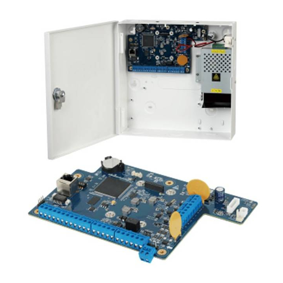
Page 20: Main Board
User’s Manual Step 3 Insert expansion bolts into the drilled screw holes, and then put in and fasten the self- tapping screws. Make sure to leave about 5 mm distance between the bottom surface of the screw head and the top surface of the expansion bolt. Step 4 Fix the controller with the screws. -
Page 21: Ports
User’s Manual Figure 2-3 Main board ports 2.3.2 Ports ● Only the professionals should be assigned to install the controller. ● Do not operate on the structural components of the controller when it is powered on. Figure 2-4 Ports... - Page 22 User’s Manual Table 2-1 Function Name Function DIP switch Restores to the factory settings. Network port Connects to Ethernet port. LINK indicator Network indicator. ACTIVE indicator Network indicator. Z1–Z8 Zone 1–Zone 8. Ground. +12V Auxiliary power output 12 VDC with 1000 mA. Ground.
-
Page 23: Dip Switch
User’s Manual Name Function DC_IN Receives 14.5 VDC power supply. Ground. Case tamper port The alarm is activated when the case is opened. 2G module Connects to 2G module Charge indicator ON: Battery is charging. ON: Battery low power. Low power indicator If power supplies normally, the indicator will not be ON in case of low battery. -
Page 24: Restoring Factory Default Settings
User’s Manual Name Function Enables to return to the factory default settings (in conjunction with DIP 5 DIP 6). Enables to return to the factory default settings (in conjunction with DIP 6 DIP 5). Enables updating the controller. ● OFF represents NOT TO UPGRADE. DIP 7 ●... -
Page 25: Wiring
User’s Manual 2.4 Wiring Figure 2-6 Wiring Figure 2-7 Wiring of detectors... -
Page 26: Startup
User’s Manual 3 Startup 3.1 Setting Keypad and Expansion Module Addresses Every keypad and expansion module registered to the controller must have a unique address. When replacing the keypad or the expansion module, the new one must use the same address as the previous one. -
Page 27: Powering On The Controller
User’s Manual Figure 3-1 Card reader connection 3.3 Powering on the Controller Power on the controller, and then the keypad registration is complete and the system enters into the normal working conditions within 75 seconds. -
Page 28: Powering On The Keypad
User’s Manual 3.4 Powering on the Keypad The keypad is registered to the controller within five seconds after it is powered on. Before registration, the LED indicators in the area 1–8 glows, and LCD display shows the keypad version information. 3.5 Factory Default Settings ●... -
Page 29: Keypad
User’s Manual 4 Keypad This chapter introduces the dimensions, main functions, indicators, keys operations, and installation of the keypad. 4.1 Dimensions Figure 4-1 Dimensions (unit: mm [inch]) 4.2 Installation Prerequisites Make sure to prepare following expansion bolts and self-tapping screws first. ●... - Page 30 User’s Manual mounting surface. Step 3 Insert expansion bolts into the drilled screw holes. Step 4 Align the holes in the rear panel of the alarm keypad with the expansion bolts, and then put in and fasten the self-tapping screws. Step 5 Attach the keypad front panel and rear panel together.
-
Page 31: Wiring
User’s Manual 4.3 Wiring Figure 4-3 keypad connection... -
Page 32: Structure
User’s Manual 4.4 Structure Figure 4-4 Structure Table 4-1 Function Name Function Displays all the system information including management LCD display and programming. For details, see "4.7 LCD Display". Displays information about power status, battery status, LED indicators failures, bypass, and alarm status of each area. For details, see "4.6 LED Indicators". -
Page 33: Numeric Keys (From 0-9)
User’s Manual Figure 4-5 Keys 4.5.1 Numeric Keys (from 0-9) The numeric keys have following functions. ● Enter access codes as required to access programming (technician or user) or to arm/disarm. ● The keys from 1 to 8 represent eight areas. When the zone is not ready, you can press and hold the key to show the NOT READY details, and when the key LED light slowly flashes or quickly flashes, press and hold the key to show the alarm details. -
Page 34: Key Combination Operations
User’s Manual Function ● Move the pointer to the left when you edit. ● Press and hold to delete the text. ● Bypass the zones as follows. 1. enter the access code. 2. Press , and then the screen of setting the bypass zones is displayed. - Page 35 User’s Manual Table 4-3 Key combination operations Function ● On the main screen, press + 0 (F0) to view the GSM connection status, which is shown with eight bars. ● Press + 0 (F0) again to return to the main screen. + 0 (F0) The system automatically returns to the main screen within 2 minutes if no operations are performed.
-
Page 36: Led Indicators
User’s Manual 4.6 LED Indicators There are 12 LED indicators on the keypad that respectively shows information about power status, battery status, faults, bypass, and alarm status of each area. 4.6.1 Overview Table 4-4 LED indicators Icon Color Meaning Green Power status. -
Page 37: Lcd Display
User’s Manual 1-8 LED Indicators There are eight LED indicators located below the LCD display representing the status of the areas. From left to right, there is the alarm status of area 1 to area 8. Figure 4-6 Area status LED indicators ●... - Page 38 User’s Manual Symbol Meaning ● H: Holiday period active. ● T: Telephone dialer calling. ● P: Disarming period for patrol user. ● S: SIA disconnect prompt. 17:30 Hour: Minutes. Level of GSM signal. Each is equivalent to one bar, and maximum eight bars. Symbols on the Second Line of Display Table 4-6 Symbols on the second line of display Symbol...
- Page 39 User’s Manual monitor the GSM signal strength during a call in progress. ● None : No GSM signal. ● One : Minimum GSM signal ● Eight : Maximum GSM signal...
-
Page 40: Expansion Module (Optional)
User’s Manual 5 Expansion Module (Optional) The expansion module is not provided, and you need to purchase it as needed. 5.1 Dimensions Figure 5-1 Dimensions (unit: mm [inch]) -
Page 41: Wiring
User’s Manual 5.2 Wiring Figure 5-2 Wiring of detectors... -
Page 42: Module Functions
User’s Manual Figure 5-3 Expansion module connections 5.3 Module Functions Dip switch addresses of the expansion modules (including alarm input and output modules) are from 1 to 8. For detailed settings, see "3.1 Setting Keypad and Expansion Module Addresses."... - Page 43 User’s Manual Alarm Input Module 8 alarm inputs and 2 alarm outputs are supported with alarm input modules. The alarm input module with Dip switch address 1 receives alarm input signals from wired zones of 9–16, and connects to alarm output devices of 3–4. Other alarm input modules are connected by analogy till the module addressed 8, which receives alarm input signals from wired zones of 65–72, and connects to alarm output devices of 17–18.
-
Page 44: Module (Optional)
User’s Manual 6 4G Module (Optional) The 4G module is not provided, and you need to purchase it as needed. 6.1 Dimensions Figure 6-1 Dimensions (unit: mm[inch]) 6.2 Installing 4G Modules Step 1 Remove two plugs on the controller. - Page 45 User’s Manual Figure 6-2 Remove plugs Step 2 Attach the thermal pad to the 4G module.
- Page 46 User’s Manual Figure 6-3 Install the thermal pad Step 3 Attach one end of the antenna patch cord to the main port of the 4G module. Step 4 Secure the 4G module to the controller with screws. Figure 6-4 Secure the 4G module Step 5 Secure the other end of the antenna patch cord to the antenna hole, and then install the external antenna on the hole.
- Page 47 User’s Manual Figure 6-5 Secure the antenna patch cord Step 6 Connect the 4G module to the 4G port on the main board with the provided wire. Step 7 Inset the SIM card into the 4G module.
-
Page 48: Installer Operations
User’s Manual 7 Installer Operations This chapter introduces the menu operations for the installer. 7.1 Entering the Installer Menu To enter the installer menu, the technician must be authorized from the user menu. The default technician code for entering the installer menu is 1961. Step 1 Enter the access code (default supervisor code is 1234), and then press The ZONE TROUBLES menu is displayed on the LCD display. -
Page 49: Installer Menu Options
User’s Manual Figure 7-3 Keypads menu 7.2 Installer Menu Options The installer menu consists of many sub menus for management and programming operations as below: ● KEYPADS ● COMMUNICATOR ● POWER SUPPLIES ● WIRED ZONES ● IN AND ZONES ● OUTPUTS ●... - Page 50 User’s Manual Step 2 Press to select which keypad you want to program, and then press enter the programming mode. + 2, you can enter the EDITING mode for changing the description of By pressing keypad. Step 3 Configure the parameters for the selected keypad. Press to alter the options.
-
Page 51: Communicator
User’s Manual Submenu Setting Select which areas the alarm from a bus communication fault between the keypad and the controller must be sent to. In practice, an acoustic alarm sounds when there is a loss of communication with the keypad (interruption in communication between the keypad and the controller). -
Page 52: Power Supplies
User’s Manual Figure 7-4 Communicator menu Step 2 Press to enter the programming mode. Step 3 Configure the parameters. Press to alter the options. Press to confirm the setting and move to the next submenu. Table 7-2 Communicator programming settings Submenu Setting There are four priority options: GSM, PSTN, GSM/PSTN, PSTN/GSM. -
Page 53: Wired Zones
User’s Manual Figure 7-5 Power supplies Step 2 Press to enter the programming mode. Step 3 Select which areas the battery alarm event must (such as main power loss, battery low voltage or missing) be sent to. Step 4 Press to return to the POWER SUPPLIES menu. - Page 54 User’s Manual You can set the zone for the most suitable type for the installation. ● INSTANT: The zone reacts to the intrusion immediately without waiting for any delay period. ● ENTRY 1 DELAY: The zone reacts after the delay 1 period is set in the AREAS menu.
- Page 55 User’s Manual Submenu Setting ● Key: The key type zone is used as an auxiliary command to arm/disarm one or more areas. ● SIREN FAULT: The siren fault zone is uses to receive abnormal output signals from the siren, and it is active for 24 hours a day. Each wired zone can be connected according to seven different criteria: ●...
- Page 56 User’s Manual Submenu Setting Each individual wired zone can be programmed to be automatically excluded or not when the area is armed if the wired zone is not ready (for example, an open window). ● NO: Establishes that the wired zone is not automatically excludable (it blocks the arming of the Area which it belongs to).
-
Page 57: Key Type Zone
User’s Manual Submenu Setting Each individual wired zone can be programmed to command a LINK type output every time it is opened. The corresponding LINK output must be then programmed in the OUTPUT menu according to actual need (status and duration). -
Page 58: In And Zones
User’s Manual ◇ FORCED ARM: Select YES or NO. If YES is selected, the key zone will be armed even though there are open zones. If NO is selected, the arming will take place only if all the area zones are ready for arming. ◇... -
Page 59: Outputs
User’s Manual Submenu Setting Select the zones that you want to combine the alarm linkage. To select the zone number, enter the number and press to confirm the input. You can also press to adjust the number. ● The IN AND ZONES can consist of any combination of wired or wireless zones and a single zone can also be placed in AND by itself. -
Page 60: Configuring Output Categories
User’s Manual Figure 7-8 Outputs Step 2 Press to enter the programming mode. Step 3 Press to select the OUT[UTS that you want to configure, and then press + 2, you can enter the EDITING mode for changing the description of By pressing OUTPUTS. - Page 61 User’s Manual Figure 7-9 Active The text ACTIVE is flashing. The output activates and remains activated manually until the is pressed. The technician then can manually test all the system outputs. Area Outputs...
- Page 62 User’s Manual Table 7-6 Areas outputs programming Submenu Setting ● AREA ON: Follows area(s) armed status. ● AREA OFF: Follows area(s) armed status. ● PART1 ON: Follows partition 1 armed status. ● PART2 ON: Follows partition 2 armed status. ● EXIT TIME: Follows the exit delay time for the assigned area. In the case of multiple areas, it follows the longest period.
- Page 63 User’s Manual Submenu Setting Select the areas (1 to 8) that you want to assign the outputs to. The areas can be assigned in individual or combined mode. In the case of multiple areas, the output is connected to them in OR or AND mode that is defined on the next screen. To assign or remove areas from the keypad, press the corresponding key (1 to 8) AREAS and then press...
- Page 64 User’s Manual Submenu Setting The zone outputs can be programmed to follow the association condition for AND and OR mode. If only one zone has been assigned, this parameter has NO value. If 2 to 4 zones have been assigned, the behavior of the output must be defined for the presentation of the event by multiple zones.
- Page 65 User’s Manual Submenu Setting Follows the setting of timers (00 to 16). The outputs can also be associated with a maximum of 4 (Start/Stop) timers which can limit the outputs operation to specific time periods TIMER1/TIMER2/ during the week. TIMER3/TIMER4 Press or directly press the value + to alter the timer...
-
Page 66: Areas
User’s Manual Item Setting The choice of the output polarity determines the at rest status of the output itself. In practice, the output can be placed in HIHG or LOW electrical status (high status gets more security) ● DIRECT POLAR ●... - Page 67 User’s Manual Figure 7-10 Areas Step 2 Press to enter the programming mode. Step 3 Press to select the AREAS that you want to configure, and then press By pressing + 2, you can enter the EDITING mode for changing the description of areas.
-
Page 68: System Functions
User’s Manual Then you can continue with programming other outputs, or press to return to the AREAS menu from where you can press to move to the next menu or press to exit from the installer menu. 7.11 System Functions Step 1 After entering the installer menu, press to scroll up and down until you reach... - Page 69 User’s Manual Submenu Setting Tamper alarm response mode. Controller tamper, siren tamper, BUS module tamper that can TAMP AL MODE generate different responses including SILENT, BUZZER, SIREN, and BUZ/SIR. Trouble alarm response mode. Set the TROUBLE ALARM (PSTN disconnection, GSM failure, TROU AL MODE antenna tamper, AC loss, battery loss, battery voltage failure, SIM expiration, time display problem) response type SILENT,...
-
Page 70: System Timing
User’s Manual Submenu Setting Password error maximum. Set the maximum allowed number of errors in code entry from the keypad (1 to 4). 00 represents there is no limit. If the maximum entry time is reached, the current keypad will be PWD ERR MAX locked for 3 minutes. -
Page 71: System Timer
User’s Manual Table 7-13 System timing settings Submenu Setting Siren alarm duration. SIR AL DUR Set the alarm lasting time of the siren. The minimum time that the bell can be set is 00:30 (30s). Siren alarm delay. SIR AL DLY Set the delay time for alarm output from siren. - Page 72 User’s Manual Figure 7-13 System timer Step 2 Press to enter the programming mode. Step 3 Configure the parameters. Press to alter the options. Press to confirm the setting and move to the next submenu. Table 7-14 System timer settings Submenu Setting ●...
-
Page 73: Access Codes
User’s Manual Then you can press to move to the next menu or press to exit from the installer menu. You will be notified 1 minute before timed arming begins, and the keypad will beep once every 2 seconds. Press to cancel arming. - Page 74 User’s Manual Step 4 Set the authority parameters. ● For supervisor and manager, you only need to set STATUS, LEVEL, ARMING, FORCED ARM, and LINK submenus. For master, user, temporary, and duress, you should set all the submenus. ● On each submenu, press to alter the options.
-
Page 75: Configuring Access Codes
User’s Manual Submenu Setting Establish whether the access code can change the zone status, for example, from ACTIVE to DISALED. ZONE STATUS ● YES ● NO Establish whether the access code can control the controller through call and SMS. ● YES REMOTE ●... -
Page 76: Deleting An Existing Access Code
User’s Manual If the code is not valid or entered incorrectly, the operation will not succeed and two beeps with the text PWD INVALID confirm the error. In this case, repeat the operation correctly. Step 3 Press to exit. 7.14.3.2 Deleting an Existing Access Code Access code 1 cannot be deleted. -
Page 77: Holiday
User’s Manual Submenu Setting Enable DST function. You can select from YES or NO. DST ENABLE Set the day and the month for the automatic change of time from Solar to SOL TO LEG Legal. Set the day and the month for the automatic change of time from Legal to LEG TO SOL Solar. -
Page 78: Telephone Number
User’s Manual + 2, you can enter the EDITING mode for changing the description of By pressing holiday. Figure 7-17 Holiday time ● 1: Holiday start day. ● 2: Holiday start month. ● 3: Holiday end day. ● 4: Holiday end month. ●... - Page 79 User’s Manual 1. On the TEL NUM submenu, press to enter the screen from where you can select a telephone number that you want to program by pressing 2. After selecting a telephone number, press to enter the programming mode. 3.
-
Page 80: Remote Service
User’s Manual Submenu Setting Press 1 to 8 to select the alarm event from which Area can be sent to AREA this SMS number. ● Press 1 to 5 to select which event can be sent to this SMS number. ●... -
Page 81: Vocal Messages
User’s Manual Figure 7-20 Monitor station Step 2 Press to select the monitor station that you want to configure, and then press Step 3 Configure the parameters. Press to alter the options. Press to confirm the setting and move to the next submenu. - Page 82 User’s Manual Table 7-21 Vocal messages settings Submenu Setting ● ACTIVE: The alarm event links this vocal message. ● ISOLATE: The vocal message linkage is programmed but temporarily STATE not used. ● OFF: The alarm event does not link this vocal message. Select a category from the following to link which you want to link the vocal message.
- Page 83 User’s Manual Submenu Setting ● If select AREA in CATEGORIES, then you can select an event from the following. When the selected event is triggered, the 2G/4G module will make a voice call to the chosen telephone number. ◇ SYSTEM TAMPER ◇...
- Page 84 User’s Manual the next menu or press to exit from the installer menu. Related Operations Procedure to Enter in the Interactive Vocal Guide Menu 1. Call the 2G/4G module equipped with the controller or receive a call from it. When 2G/4G module is called and answer to voice broadcast Please input the password. 2.
-
Page 85: Sms Messages
User’s Manual Figure 7-23 Voice prompts during entering password process 7.21 SMS Messages If equipped with the 2G/4G module, the alarm controller is able to transmit and receive SMS as command and request to state. Step 1 After entering the installer menu, press to scroll up and down until you reach the SMS MESSGAES menu. - Page 86 User’s Manual Table 7-22 Smartphone sending SMS to controller Content replied by Meaning Command (Content by smartphone) controller automatically Area Status (22/05/2018 Some Area Total 1234 TOTAL 1 2 3 13:13)–Area ON:123-Area OFF:45678 Area Status All Areas Total (22/05/2018 1234 TOTAL 13:13)–Area ON:12345678 P1 Status...
- Page 87 User’s Manual Table 7-23 Controller sending SMS to smartphone Meaning Note Content by controller Alarm Info (22/05/2018 4.1.1 Wired zone1 alarm 13:13)–Z1_Area:12345678 Alarm Info (22/05/2018 13:13)– Wired zone1 tamper 4.2.1 alarm Tamper_Area:12345678 Alarm Info (6/12/2018 Wired zone1 water leak 4.3.1 11:9)-WATERLEAK alarm ALARM:Z1_AREA: 1...
- Page 88 User’s Manual Meaning Note Content by controller System Restore (22/05/2018 13:13)– 4.9.2 TCP/IP Network Restore TCP/IP Network Restore Module Info (22/05/2018 13:13)– 4.10.1 Keypad1 Failure Keypad1 Failure Module Restore (22/05/2018 13:13)– 4.10.2 Keypad1 Restore Keypad1 Restore Module Info (22/05/2018 13:13)– 4.10.3 Input1 Failure INPUT1 Failure...
-
Page 89: Digital Format
User’s Manual Meaning Note Content by controller Emergency Info (22/05/2018 13:13)– Triggered by zone1 Fire Alarm:Z1_Area:12345678 Area Status (22/05/2018 User4 is 13:13)– 4.16.1 User4 Arm Marguerite, she Area ON:12345678 by total arms Marguerite Area Status (22/05/2018 User4 is 13:13)– 4.16.2 User4 Disarm Marguerite, she Area OFF:12345678 by... - Page 90 User’s Manual number linkage setting screen is shown. ● PSTN TEL1, PSTN TEL2, PSTN TEL3: Three telephone numbers mentioned in Monitor Station menu. ● TRUE: Links this telephone number ● FALSE: Does not link this telephone number. Figure 7-27 Telephone number linkage Table 7-25 Digital format setting Category Event No.
- Page 91 User’s Manual Category Event No. Setting CID Code Medical Alarm Fire Alarm Water Leak Alarm Rapid Arming Partial 1 Arming Key Input Arming Key Input Disarming Monitor Arming Monitor Disarming Force Arming Arming Failure Timer Arming Failure Arming/Disarming Exit Delay Report Code Arming Failure Group...
- Page 92 User’s Manual Category Event No. Setting CID Code The CID code changes automatically according to the type of protection zone. ● Wired Zone Instant Alarm: 130 ● Wired Zone Fire Alarm: 110 ● Wired Zone Medical Alarm: 100 ● Wired Zone Panic Alarm: 120 Wired Zone 1-8 346-353 ●...
-
Page 93: Tcp/Ip Network
User’s Manual 7.23 TCP/IP Network Step 1 After entering the installer menu, press to scroll up and down until you reach the TCP/IP NETWORK menu. Figure 7-28 TCP/IP Network Step 2 Press to enter the programming mode. Step 3 Configure the programming settings. Table 7-26 TCP/IP network settings Submenu Settings... -
Page 94: 4G Module
User’s Manual the LOG EVENT menu. Figure 7-29 Log event Step 2 Press to enter the submenu that shows the latest stored event. Figure 7-30 The latest stored event ● The first line shows the event with its number and the date and time. ●... -
Page 95: Language
User’s Manual 7.26 Language Step 1 After entering the installer menu, press to scroll up and down until you reach the LANGUAGE menu. Figure 7-32 Language Step 2 Press to enter the programming mode. Step 3 Press to select a system language Step 4 Press to return to the LANGUAGE menu. -
Page 96: Expansion Modules
User’s Manual Table 7-28 RFID card parameter descriptions Submenu Descriptions Set the card to an operating or non-operating status. ● A: Active. The RFID card is in normal condition STATE ● I: Isolate. The RFID card cannot be used, and can be activated again after switched to ACTIVE state. -
Page 97: Sia
User’s Manual Figure 7-34 Expansion module Step 2 Press to enter the programing mode. Figure 7-35 Input module Press to select input module or output module. Step 3 Press to enter the module setting screen. Figure 7-36 Module setting ● Press to select one module or you can press the module number and then press to go to desired module directly. - Page 98 User’s Manual The SIA must be customized according to different platforms. Step 1 After entering the installer menu, press to scroll up and down until you reach the SIA menu. Figure 7-38 SIA Step 2 Press to enter the programming mode. Step 3 Press to select YES/NO to enable or disable the SIA, and then press...
- Page 99 User’s Manual Figure 7-42 Enter account number Step 7 Press , and then go to ENCRYPTION to set the account name. NONE is select by default. Figure 7-43 Enter account number Step 8 Press , and then go to HEARTBEAT to set the heartbeat. Heartbeat ranges from 1 to 65535.
- Page 100 User’s Manual Figure 7-46 Enable heartbeat Step 11 To enable AES128, press , and then go to KEY to set the keys. The key must contain 32 characters, with numbers from 0-9 and characters from A-F. Figure 7-47 Set keys Step 12 (Optional) To set more SIA, press , and then go to SIA settings, and repeat the above procedures.
-
Page 101: Alarm Config Tool
User’s Manual 8 Alarm Config Tool The alarm config tool is for installers to configure alarm control parameters. 8.1 Home Page Figure 8-1 Home page Table 8-1 Main interface introduction Name Description Includes two menus: Setting and Update Device. For details, Menu see "8.2 Setting"... -
Page 102: Setting
User’s Manual Name Description Displays the functions tabs of Setting that you can configure or Function tabs view. 8.2 Setting In the Setting module, you can configure parameters that are related to clients, utility, installers and language. 8.2.1 Client In this section, you can search, manage, and configure parameters for clients. 8.2.1.1 Managing a Client You can add new clients, modify, copy, and delete client information. -
Page 103: Modifying A Client
User’s Manual ● Communication: Displays computer IP address and controller IP address and port. ● User Info: You can enter two users’ names, addresses, telephone numbers and more. ● client Note: You can record your operation histories. ● The Security Code is set by the user under User Menu > Security Code on the keypad, and you need to ask for it in advance. -
Page 104: Configuring Client Parameters
User’s Manual Figure 8-3 Client Step 2 Enter the searching options. Step 3 Click Search. The clients whom you want to search for will be shown. 8.2.1.3 Configuring Client Parameters Activator In Activator, you can configure parameters for keypads and access codes. Keypads On the client interface, select Activator >... - Page 105 User’s Manual Figure 8-5 Access codes RFID Cards On the client interface, select Activator > RFID Cards, and the RFID Cards page is shown. You can start configuring the parameters as needed, and the settings will be effective in real time. For details, see "7.27 RFID Cards".
- Page 106 User’s Manual Figure 8-8 Expansion module In I/O, you can configure parameters for Wired Zones, IN AND ZONES, and Output. Wired Zones On the client interface, select I/O > Wired Zones, and the Wired Zones page is shown. You can start configuring the parameters if needed, and the settings will be effective in real time.
- Page 107 User’s Manual "7.9 Outputs". Figure 8-11 Output System In System, you can configure parameters for Areas, SYS Functions, 2G/4G SYS Timings, Timers, and Holidays. Areas On the client interface, select System > Areas, and the Areas screen is shown. You can start configuring the parameters if needed, and the settings will be effective in real time.
- Page 108 User’s Manual Figure 8-13 SYS functions 2G/4G On the client interface, select System > 2G/4G, and the 2G/4G page is shown. You can start configuring the parameters if needed, and the settings will be effective in real time. For details, see "7.25 2G/4G Module".
- Page 109 User’s Manual Figure 8-16 Timers Holidays On the client interface, select System > Holidays, and the Holidays page is shown. You can start configuring the parameters if needed, and the settings will be effective in real time. For details, see "7.16 Holiday".
- Page 110 User’s Manual Figure 8-19 Telephone No. You can select Voice, SMS, or SMI Number as Telephone No. type. Vocal Message On the client interface, select Communication > Vocal Message, and the Vocal Message page is shown. You can start configuring the parameters if needed, and the settings will be effective in real time.
- Page 111 User’s Manual start configuring the parameters if needed, and the settings will be effective in real time. For details, see "7.19 Monitor Station". Figure 8-22 SYS event Module Event On the client interface, select Digital Port > Module Event, and the Module Event page is shown. You can start configuring the parameters if needed, and the settings will be effective in real time.
- Page 112 User’s Manual Arm/Disarm Event On the client interface, select Digital Port > Arm/Disarm Event, and the Arm/Disarm Event page is shown. You can start configuring the parameters if needed, and the settings will be effective in real time. For details, see "7.19 Monitor Station". Figure 8-25 Arm/disarm event Zones Event On the client interface, select Digital Port >...
-
Page 113: Utility
User’s Manual Figure 8-27 Log events Table 8-2 Functions of buttons Name Function Click Read Main Panel, you can read logs recorded in the Read main panel alarm controller. Click Read Archived, you can read logs that were saved to Read archived your computer. -
Page 114: Installer
User’s Manual Figure 8-29 Import/Export 8.2.3 Installer Click Installer, and the Input Installer Code box is shown. You can input the installer code. Figure 8-30 Input installer code 8.2.4 Language Click Language, and the Language box is shown. You can select English, Italian, or Spanish. Figure 8-31 Language 8.3 Updating Device Step 1... - Page 115 User’s Manual Click Select File to select the corresponding upgrading file for Panel, Keypad, Input Step 4 Module, and Output Module. Click Start Update and then follow the onscreen instructions to complete upgrading. Step 5...
-
Page 116: Dmss App Operations
User’s Manual 9 DMSS App Operations You can remotely manage the alarm controller on DMSS app. 9.1 Installing the App Download the DMSS app in the Google Play (Android OS) or app store (iOS). 9.2 Adding Alarm Controller Enable P2P function on the alarm controller, otherwise, the device cannot be accessed to DMSS app. For details, see "7.25 2G/4G Module". -
Page 117: Area Arming And Disarming
User’s Manual Figure 9-2 Add device to the app (2) You can also add the device by entering device IP, or searching the online device. 9.3 Area Arming and Disarming This section uses arm area 1 as an example. Step 1 On the Home screen, tap the added alarm controller. - Page 118 User’s Manual Figure 9-3 Start operations Tap Disarm or Arm on the top of the screen to disarm/arm all the areas displayed below at the same time. For details, see "7.14 Access Codes". On the device operation screen, tap Area 1. Step 2...
-
Page 119: Zone Settings
User’s Manual Figure 9-4 Area 1 Select arming type from Total, P1, and P2. P1 and P2 can be selected at the same time. Step 3 To disarm the area, on the Area 1screen, tap Disarm. Step 4 9.4 Zone Settings This section uses zone 1 under area 1 as an example. -
Page 120: Configuring Device On App
User’s Manual Figure 9-5 Zone 1 Step 3 Configure the zone 1 parameters. ● Protection Zone Name: Tap it to edit the zone name, for example, enter Front Gate. ● Detector Status: Indicates the detector status that includes normal, open, tamper, anti- mask, and short-circuit. - Page 121 User’s Manual alarm messages will be displayed on Message screen after the alarm is triggered. ● PGM: Tap to configure siren and other alarm outputs. Tap open/close on the right to enable or disable siren output and other alarm outputs. ●...
-
Page 122: Configuring Area
User’s Manual Figure 9-7 Siren output 9.5.2 Configuring Area This section uses configuring area 1 as an example. On the Home screen, tap the added alarm controller. Step 1 Step 2 On the device operation screen, tap Area 1. Step 3 at the upper-right corner to enter the device details screen. -
Page 123: Faq
User’s Manual 10 FAQ 1. Q: The alarm controller does not start after it is powered on. A: The possible reasons are as below. ● Power input is incorrect. ● AC adapter damage that results in there being no 14.5 VDC output. ●... - Page 124 User’s Manual 9. Q: The battery cannot be charged, or it cannot be fully charged, or it charges too slowly. A: The possible reasons are as below. ● The adapter that you are using is not the original or the output voltage is not 14.5V DC. ●...
-
Page 125: Appendix 1 Keypad Buzzer Sound
User’s Manual Appendix 1 Keypad Buzzer Sound Appendix Table 1-1 Keypad sound Description Buzzer sound Keypad pressing. One slight beep Menu entering. One beep ● Switching between the first menu and the last menu after log in to the system. Continuous three beeps ●... -
Page 126: Appendix 2 Event Log Messages
User’s Manual Appendix 2 Event Log Messages Appendix Table 2-1 Event log messages Event message Description Event message Description AL.SF Siren Fault P1.Arm Partitial1 Arm Alarm P2.Arm Partitial2 Arm S.T.RES Siren Tamper Restore AL.PAN. Panic Alarm AL.S.T Siren Tamper Alarm AL.ROB. - Page 127 User’s Manual Event message Description Event message Description System Battery Low SYS.BAT.Low.VOL. WLI.M.T Voltage Wireless Input Module Tamper System Battery SYS.BAT. Restore WL.IN.MODU.TAM Restore Wireless Input SYS. System WL IN.Module Module RES. Restore When the following faults occur at the same time, the priority is as follows: A>B>C>D>E. In the same level, the subsequent time will be reported first.
-
Page 128: Appendix 3 Installer Menu Map
User’s Manual Appendix 3 Installer Menu Map Appendix Table 3-1 Installer menu map KEYPADS Keypad 1–8 STATE AREA SHOW EVENTS TAMPER TROUBLE RAPID ARMING FORCED ARM BUZ.ON/OFF BUZ.ENTRY BUZ.EXIT BUZ.ALARM BUZ.CHIME KEYPAD BEEP BACKLIGHT BUS ERRORS COMMUNICATOR PRIORITY ATTEMPTS PSTN TROU GSM TROU SIM TYPE PREFIX OPTION... - Page 129 User’s Manual TERMINATION AREA BYPASS PARTITION1 PARTITION2 AUTO BYPASS ALARM ALARM CYCLE ALARM REPEAT OUTPUT LINK IN AND ZONES IN AND ZONE 1–8 STATE ZONE1 ZONE2 IN SEQUENCE TRIGGERS AND TIME OUTPUTS Output 1–82 STATE CATEGORIES AREAS ZONES LINK GENERIC SYSTEM TYPE POLAR...
- Page 130 User’s Manual TIMER 1 TIMER 2 TIMER 3 TIMER 4 client ID SYSTEM FUNCTIONS MAX AL CYCLE SYS AL CYCLE PANEL TAMPER SIREN TAMPER TAMP AL MODE TROU AL MODE COM TROU AL ARM DLY AL ENY/EXT BEEP PANIC AL MOD DURESS MOD PWD ERR MAX FACTORY RST...
- Page 131 User’s Manual TYPE START TIME STOP TIME DAYS HOLIDAYS ARMING FORCEDARM ACCESS CODES Access Code 1–99 STATE LEVEL ARMING FORCED ARM LINK1 LINK2 LINK3 LINK4 NEW CODE DATE/TIME TIME DATE DST ENABLE SOL TO LEG LEG TO SOL EXPIRE HOLIDAY Holiday 1–20 TIME TEL NUMBER...
- Page 132 User’s Manual CREDIT SMS TIME AREA EVENT SIN NUM REMOTE SERVICE STATE MONITOR STATION Monitor 1–3 STATE MODE TEST DATE TEST TIME VOCAL MESSAGES Vocal message 1–88 STATE CATEGORIES AREA ZONE SYSTEM SMS MESSAGES SMS message 1–377 DIGITAL FORMAT TCP/IP NETWORK DHCP IP ADDRESS SUBNET...
- Page 133 User’s Manual AREAS ARMING FORCED ARM ARMING METHOD PASSWORD PLEASE SWIPE EXPANSION MODULE INPUT MODULE 1–8 TROUBLE OUTPUT MODULE 1– TROUBLE SIA1-2 ENABLE IP ADDRESS PORT ACCOUNT ENCRYPTION HEARTBEAT INTERVAL ENABLE HEARTBEAT...
-
Page 134: Appendix 4 Cybersecurity Recommendations
IP video surveillance is not immune to cyber risks, but taking basic steps toward protecting and strengthening networks and networked appliances will make them less susceptible to attacks. Below are some tips and recommendations from Dahua on how to create a more secured security system. - Page 135 User’s Manual 1024–65535, reducing the risk of outsiders being able to guess which ports you are using. 6. Enable HTTPS We suggest you to enable HTTPS, so that you visit Web service through a secure communication channel. 7. MAC Address Binding We recommend you to bind the IP and MAC address of the gateway to the device, thus reducing the risk of ARP spoofing.
- Page 136 User’s Manual device. More information Please visit Dahua official website security emergency response center for security announcements and the latest security recommendations.
- Page 137 User’s Manual...
Need help?
Do you have a question about the DHI-ARC3008C and is the answer not in the manual?
Questions and answers