Table of Contents
Advertisement
Quick Links
Advertisement
Table of Contents

Related Manuals for Instron 6800


Summary of Contents for Instron 6800
- Page 1 6800 Dual Column Retrofit Operator’s Guide M10-17547-EN Revision B...
- Page 2 Instron is a registered trademark of Illinois Tool Works Inc. (ITW). Other names, logos, icons and marks identifying Instron products and services referenced herein are trademarks of ITW and may not be used without the prior written permission of ITW.
- Page 3 Caution is used where a hazard may lead to damage to equipment or to loss of data. Instron products, to the best of its knowledge, comply with various national and international safety standards, in as much as they apply to materials and structural testing.
- Page 4 Preliminary Pages Warnings Hazard - Press the Emergency Stop button whenever you consider that an unsafe condition exists. The Emergency Stop button removes hydraulic power or electrical drive from the testing system and brings the hazardous elements of the system to a stop as quickly as possible.
- Page 5 During system operation, keep away from the operating envelope of the robot. De-activate the robot before entering the envelope for any purpose, such as reloading the specimen magazine. Product Support: www.instron.com...
- Page 6 Preliminary Pages Warnings Hazard - Set the appropriate limits before performing loop tuning or running waveforms or tests. Operational limits are included within your testing system to suspend motion or shut off the system when upper and/or lower bounds of actuator or crosshead travel, or force or strain, are reached during testing.
- Page 7 Apply the specified torque to all load string fasteners and the correct setting to wedge washers or spiral washers. Visually inspect highly stressed components such as grips and threaded adapters prior to every fatigue test for signs of wear or fatigue damage. Product Support: www.instron.com...
- Page 8 Preliminary Pages M10-17547-EN...
-
Page 9: Table Of Contents
Operator Protection Overview ..........Product Support: www.instron.com... - Page 10 Preliminary Pages Chapter 4: Installation ..........39 Power supply compatibility.
- Page 11 Parts list ............Product Support: www.instron.com...
- Page 12 Preliminary Pages Index ............. . . 105 M10-17547-EN...
-
Page 13: Chapter 1: Preinstallation Information
Retrofit Controller can be placed on either side of the load frame or on a bench or shelf adjacent to the load frame • the cables connecting the load frame to the Retrofit Controller are 3 m (9.8 ft) long • the Retrofit Controller power cable is 2.5 m (8.2 ft) long Product Support: www.instron.com... -
Page 14: Bluehill ® Operator Dashboard
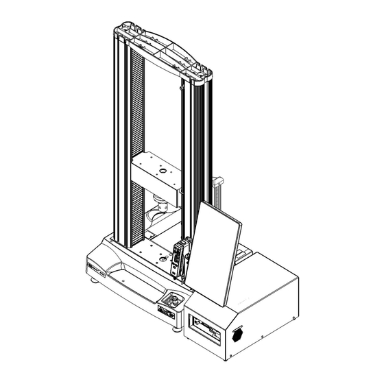
Chapter: Preinstallation information ® Bluehill Operator Dashboard Figure 1. Frame dimensions - including dashboard ® The weight of the Bluehill Operator Dashboard and its mounting kit is 2.4 kg (5.2 lb). M10-17547-EN... -
Page 15: 68Tm-Retrofit Power Requirements And Cords
RCD protection on all power sources to protect the operator from fluids that might leak into the load frame electronics. Power cord selections ® If you do not make a choice, Instron chooses the customary power cord that matches the shipping destination for the system. Product Support:... - Page 16 Chapter: Preinstallation information Table 2. Power cords Power cord designation Matching receptacle Locale USA and Canada Denmark Europe Italy China Australia and New Zealand Switzerland M10-17547-EN...
- Page 17 68TM-Retrofit Power Requirements and Cords Table 2. Power cords (Continued) Power cord designation Matching receptacle Locale United Kingdom (includes 10A fuse) India and South Africa Product Support: www.instron.com...
- Page 18 Chapter: Preinstallation information M10-17547-EN...
-
Page 19: Chapter 2: Introduction
(carried out by an ® Instron service engineer for first-time installation) • ® configuring the system before you start testing (carried out by an Instron service engineer for first-time installation) • spare parts Using these instructions you will be able to: •... -
Page 20: System Description And Terminology
Chapter: Introduction ® These instructions do not include the development of Bluehill test methods. This is ® covered in more advanced training that can be provided by the Instron Service and Training departments. System Description and Terminology ® Figure 2. -
Page 21: Components
Existing dual column load frame (5900 frame shown) ® Bluehill Operator Dashboard (optional) Retrofit Controller Controller panel Emergency stop button Indicator panel New cover on frame base Handset Components ® The major components of an Instron retrofit electromechanical testing system include: Product Support: www.instron.com... - Page 22 ® contacting extensometer. Contact your regional Instron office or check our web site at www.instron.com for assistance with Instron’s grips and fixtures. The following table defines the components of the testing system: Table 3. Testing System Components Component...
-
Page 23: Principle Of Operation
Handset - holds all the controls for the testing system. Software ® Control of the testing system is carried out via Instron Bluehill software. Setting test parameters, operating the system, and collecting test data is done through the software program. -
Page 24: System Safety And Information Labeling
Chapter: Introduction Table 4. Software Terminology (Continued) Term Description Sample A group of material specimens, whose properties are studied and compared to gain statistical or quality assurance information. For example, you could take a specimen from different parts of a single manufacturing run of a material to form a sample of the material. - Page 25 Read the manual Read and understand the operator’s manual before using the machine. Crosshead direction Indicates the direction to turn the pulley to manually move the crosshead upward. Pulleys can be turned by hand when power is disabled. Product Support: www.instron.com...
-
Page 26: Product Support
® If you cannot find answers in these sources, contact Instron Service directly. A list of ® Instron offices is available on our website at www.instron.com. In the US and Canada, you can call directly at 1-800-473-7838. M10-17547-EN... -
Page 27: Product Documentation
® Instron offers a comprehensive range of documentation to help you get the most out of your Instron products. Depending on what you have purchased, your documentation may include some or all of the following: Operator’s Guide How to use your system components and controls, procedures for setting limits, calibration and other frequently performed operating tasks. - Page 28 Chapter: Introduction M10-17547-EN...
-
Page 29: Chapter 3: Risk Reduction And Safe Use
Each of the following sections describes a specific hazard zone of the testing system and lists the most common risks for testing using this equipment. Use the information in the following sections, together with the instructions in the remainder of this manual, to conduct your own risk assessment. Product Support: www.instron.com... -
Page 30: Rapid Crosshead Motion
Chapter: Risk reduction and safe use Rapid crosshead motion Warning Crush hazard to fingers or hands. This hazard relates to grips and fixtures coming together as a result of rapid crosshead motion, crushing hands or fingers. For example, an operator inadvertently commands the system to jog or return while their hands are in test area. - Page 31 Use a specimen insertion tool to keep fingers out of the space between the fixtures. • Use an interlocked shield to limit or disallow motion when the shield door is open. When the space is less than 25mm, the crush hazard is very significant, so this is the best option. Product Support: www.instron.com...
-
Page 32: Pinching Fingers Between Grip Jaw Faces
Chapter: Risk reduction and safe use Pinching fingers between grip jaw faces Warning Pinch hazard to fingers. This hazard relates to grip jaws closing quickly, pinching fingers. Recommendations For 2712 Series pneumatic grips: • In the documentation supplied with the grips, read and follow the safety recommendations for installing a specimen. -
Page 33: Impact Of Debris From Breaking Specimens
This hazard relates to brittle or composite specimens that can explode when they break. Recommendations For less dangerous debris (specimen dust or fibers, for example): • Use personal protection equipment (for example safety glasses). For more dangerous projectile debris (brittle composite specimens, for example): • Use an interlocked shield. Product Support: www.instron.com... -
Page 34: Collision Mitigation
Chapter: Risk reduction and safe use Collision Mitigation The 3400 and 6800 Retrofit Series systems are equipped with the Collision Mitigation feature to help reduce accidental equipment and specimen damage. Collision Mitigation enables the retrofit system to continually monitor force during jog and return operations, and will automatically stop the crosshead movement if an unexpected force is detected. -
Page 35: Solid Particle Ingress
Clean the testing system and adjacent areas frequently with a vacuum or soft brush to prevent any accumulation of debris. • ® As part of periodic maintenance, contact Instron Service to inspect the inside of the testing system for accumulation of debris, and clean it if necessary. •... -
Page 36: Operator Protection Overview
(if present) and any installed accessories. ® 3. If you have reason to believe that liquid entered the testing system, contact Instron Service. The service engineer will remove the covers of the equipment and clean up all traces of spilled liquid. - Page 37 Access to the controls for Operator Protection is password protected. If you have ® Administrator rights you can modify Operator Protection in the Admin tab in Bluehill Refer to “Operator Protection” on page for more details. Product Support: www.instron.com...
- Page 38 Chapter: Risk reduction and safe use M10-17547-EN...
-
Page 39: Installation
The equipment voltage is compatible with the main power supply of your facility. Refer to “Determine the voltage setting” on page 41. • The equipment power cable can reach the electrical power supply with some slack in the cable. • The plug is compatible with the electrical power outlet. Product Support: www.instron.com... -
Page 40: Set The Input Voltage
Chapter: Installation If your power source is not the voltage originally specified on your purchase order, you can follow the instructions in “Change the voltage setting” on page to change the voltage. Ensure that you use the appropriate electrical plug when changing voltages. Warning Hazard - Do not remove covers to any component of your system, unless it is specified in a procedure. - Page 41 This situation may arise if the system is moved to another location with a different voltage from the factory setting on the equipment. You will need the following equipment (not supplied): • Small flat-head screwdriver or probe • Long-nose pliers Product Support: www.instron.com...
- Page 42 Chapter: Installation Warning Electrical hazard - shut off the main power switch and disconnect the power to the Retrofit Controller before changing the power setting. There are dangerous voltage levels inside the fuse holder. Warning Hazard - Do not remove covers to any component of your system, unless it is specified in a procedure.
-
Page 43: System Components
51. System components ® Instron Service installs your testing system. These diagrams and instructions are provided as a reference if you need to move the system after the initial installation. The Retrofit Controller houses all the components required to control the testing system, taking over all control functions from the original load frame, including the power input connector. -
Page 44: Load Frame Connections
Chapter: Installation Load frame connections Version 1 Figure 7. Frame connections Legend for Figure 7 Label Component More detail Motor feedback (encoder) connection Matching connection 1 shown Figure 9 FEEDBACK Connection for Indicator panel Matching connection 4 shown Figure 9 PANEL Connection for motor power Matching connection 5 shown... -
Page 45: Retrofit Controller
A set of connectors on the rear panel of the Retrofit Controller connect to the original load frame. The controller panel on the front of the Retrofit Controller replaces any controller panel on the original frame for the connection of transducers and accessories. Product Support: www.instron.com... - Page 46 Chapter: Installation Rear panel connections detail Figure 9. Rear panel connections detail Legend for Figure 9 Label Component More detail Pneumatic grips - grip 1 connector (typically upper grip) Pneumatic grips - grip 2 connector (typically lower grip) Pneumatic grips - air inlet connector 120 psi (8.3 bar) maximum M10-17547-EN...
- Page 47 Do not connect the two exhaust ports together. In some situations, unexpected grip motion can result. To prevent this, do not link the exhaust ports (for example with a “T” or “Y” fitting). The two exhaust ports must remain separate. Product Support: www.instron.com...
- Page 48 AutoX extensometers Foot switch connector Status indicators PIP jack Strain connectors Optional Status indicators Force connector Connects to load cell Sync connector ® Service connectors For use by Instron Service only Expansion connector Optional I/O (Input/Output) connector Optional M10-17547-EN...
-
Page 49: Bluehill ® Operator Dashboard
® testing machine using Bluehill software. Adjustment and connection ® ® Instron Service will install the Bluehill Operator Dashboard on your system. ® 1. You can adjust the height of the Bluehill Operator Dashboard for the comfort of different operators. Loosen the lock (1 in... - Page 50 Chapter: Installation Disconnection and moving ® If you need to move the testing system you must disconnect and remove the Bluehill Operator Dashboard as follows: 1. Ensure that the power switch is set to Off and the mains power cable is disconnected. ®...
-
Page 51: First Time Startup
Operator Dashboard face down on a soft material to avoid scratching the screen. First time startup ® When the testing system is installed, you need to configure Bluehill to communicate with the testing hardware. 1. Ensure that all cables are properly installed and securely connected. Product Support: www.instron.com... - Page 52 Chapter: Installation 2. Turn the power switch on the machine to the On ( ) position. The white LED above the DISABLED indicator flashes. ® 3. Turn on the power to the Bluehill Operator Dashboard and any other accessories that make up the testing system. ®...
-
Page 53: Chapter 5: Function Of Controls
Pneumatic Grips ........... 72 Before you start the system, make sure you familiarize yourself with the following controls: Product Support: www.instron.com... -
Page 54: Power Input Connector
Chapter: Function of controls Power input connector Figure 14. Power input connector Legend for Figure 14 Label Component IEC inlet connector Power switch Selected voltage Fuse carrier and voltage selector access The power input connector, shown in Figure 14 on page 54, performs the following functions: •... -
Page 55: Emergency Stop Button
All the controls for the testing system are on the handset. When you operate a control on the handset, any change to the testing mode is displayed on the indicator panel (refer to “Indicator Panel” on page 58). Product Support: www.instron.com... - Page 56 Chapter: Function of controls Figure 16. Handset Legend for Figure 16 Label Description Softkeys 1 and 2 These softkeys duplicate the functions assigned to Softkey 1 and 2 in ® Bluehill software. Buttons illuminate white when available. M10-17547-EN...
- Page 57 Press this button to toggle on or off the SPECIMEN PROTECT function. This function protects the test specimen and load string components from overloads. Button illuminates white when available and changes to green when you activate it. Product Support: www.instron.com...
-
Page 58: Indicator Panel
Chapter: Function of controls Label Description ZERO DISPLACEMENT button Press this button to set the current position of the crosshead as the zero displacement point (or gauge length) position. After setting the zero displacement point, the crosshead returns to this position when: •... -
Page 59: Bluehill ® Software
SET UP (blue) • (yellow) CAUTION • TESTING (red) ® Bluehill software The software controls: • setting test parameters • collecting and analyzing test data ® Refer to the Bluehill online help and reference for more details. Product Support: www.instron.com... -
Page 60: Home Screen
This button is hidden if Security is not enabled. ® Instron Connect Uses an Internet connection to check the status of the system, including verification status of transducers. Checks for software updates. - Page 61 Method - the name of the current method file that is open, if any. • Report - the name of the current report template that is open, if any. • Progress messages - various messages indicating progress, for example “Opening”, “Closing” and “Generating”. Product Support: www.instron.com...
-
Page 62: Operator Protection
Chapter: Function of controls Operator Protection ® Operator Protection in Bluehill provides a mechanism that lets you limit crosshead jog speed and reduce grip closing pressure while you are setting up a test. Operator Protection lets an Administrator configure the testing system to be consistent with the risk assessment for that system. - Page 63 (no greater than 600 mm/min) • pneumatic grips can close at the initial grip pressure (default value of 15 psi) The frame returns to set up mode when: Product Support: www.instron.com...
- Page 64 Chapter: Function of controls • the test is paused (e.g. during extensometer removal) • after a test is complete • after a return is complete • when an interlocked shield is opened To proceed to CAUTION mode, you press the UNLOCK button.
-
Page 65: Move Between Modes
Crosshead speed ramps up gradually to the maximum speed of the frame. Move between modes The following table shows how the controls on the handset move the system between modes to set up and run a test. Product Support: www.instron.com... - Page 66 Chapter: Function of controls Table 7. Move between modes Initial condition Action Result DISABLED SET UP Press (white) (blue) System remains in set up mode until you make a change. During this time you can: • move the crosshead at the restricted speed set up in the Admin tab, up to a maximum of 600 mm/min •...
- Page 67 If you are using toggle switches on the grips to control them, the grips are at full pressure only during TESTING mode. Typical test flow “Move between modes” on page describes each of the test controls and how they are used to move between testing modes. Product Support: www.instron.com...
-
Page 68: Jog At High Speed
Chapter: Function of controls For a step-by-step description of a typical test flow using these controls, refer to “Testing a sample” on page 81. This section contains two procedures, one for systems using an interlock and one for systems without an interlock. Jog at High Speed Under normal conditions, in SET UP... -
Page 69: Operator Protection Controls
The interlock automatically transitions the system to CAUTION mode when the interlock is closed. If there is no interlock, you must press the UNLOCK button to transition to CAUTION mode. Product Support: www.instron.com... -
Page 70: Bluehill ® Operator Dashboard
Chapter: Function of controls Control Description Pneumatic grips Enables and disables pneumatic grips connected to the testing system with the integrated air kit. Grip control Footswitch (when pneumatic Default is . You close both grips using the grips are enabled) integrated air kit and foot switch. -
Page 71: Basic Touch Functions
(landscape orientation) to display a panel that lets you quickly include or exclude a specimen from the sample • any scrollable screen component - flick up or down, left or right to quickly scroll through the list Product Support: www.instron.com... -
Page 72: Pneumatic Grips
Other pneumatic grips can be used with the system, including operation with the integrated air kit and footswitch, but they may not be designed to utilize the full range of ® features of Operator Protection. Contact Instron Service for advice. M10-17547-EN... -
Page 73: How Operator Protection Works With Grips
This may cause a hazard when the grips transition to full pressure. If the grips do not close completely at the initial pressure, they will close at full force when the grips transition to full pressure. Product Support: www.instron.com... - Page 74 Chapter: Function of controls Warning If the grips feature an air inlet flow adjustment control (see below), make sure that the flow adjustment is set to fully open (screw fully counterclockwise). Do not use the air inlet flow adjustment control to reduce air flow as you risk transitioning from initial pressure to full pressure before the grips have closed.
-
Page 75: Operate Grips Using Footswitch
3. Press the UNLOCK button to transition to CAUTION mode. The grips pressurize to full pressure. Product Support: www.instron.com... -
Page 76: Operate Grips Using Toggle Switches
Chapter: Function of controls 4. Within 2 seconds, press the START TEST button to start the test. If you do not start the test immediately and the system returns to SET UP mode, the grips continue at full pressure until you run a test or release the grips. The system transitions to TESTING mode. - Page 77 The system transitions to TESTING mode and the grips pressurize to full pressure. 6. Stop the test, or the test ends. The system reverts to SET UP mode and the grip pressure returns to the initial grip pressure. Product Support: www.instron.com...
-
Page 78: Grips Not In Use
Chapter: Function of controls Caution If your test ends and the specimen has stored energy, e.g. the specimen did not break, the specimen may slip out of the grips when the grip pressure reduces at the end of the test. If this could be an issue, it is recommended that you set the point of control for grips to Footswitch and use a footswitch for your tests. -
Page 79: Chapter 6: Assemble The Load String
It includes the load cell, grips, the specimen and any adapters that let you connect any of these components together. ® Instron Service sets up the testing machine during installation, but you may need to change one or more of these components for different types of testing. - Page 80 Chapter: Assemble the load string M10-17547-EN...
-
Page 81: Chapter 7: Testing Specimens
An interlock is an optional accessory that changes the behavior of the system depending on whether the interlock circuit is open or closed. For example, the door on a protective shield may include an interlock. When the interlock circuit is open (e.g. the Product Support: www.instron.com... -
Page 82: Testing With No Interlock
Chapter: Testing specimens shield door is open), the circuit is interrupted and the system is either disabled or restricted as defined by the Operator Protection settings. Testing with no interlock This test scenario assumes the system has no accessories with an interlock and that the start test method in Operator Protection settings is set to Frame control (the default). - Page 83 11. Use the jog controls to move the crosshead to its starting position and set zero displacement. Refer to “Set the zero displacement point” on page 93. 12. Balance the Force transducer configuration. Refer to “Balance a transducer configuration” on page Product Support: www.instron.com...
- Page 84 Chapter: Testing specimens 13. Install the specimen into the grips. Refer to the documentation provided with the grips for details. If the system includes pneumatic grips, refer to “Pneumatic Grips” on page 72. 14. Verify that the specimen is aligned properly in the grips. 15.
-
Page 85: Testing With An Interlock
The high energies involved in testing can cause broken parts of a specimen to be projected forcefully some distance from the test area. Wear eye protection and use protective shields or screens whenever a risk of injury to operators and observers exists from the failure of a test specimen. Product Support: www.instron.com... - Page 86 Chapter: Testing specimens Select the correct test area for the test. An incorrectly set test area can cause unanticipated crosshead behavior. Press the Emergency Stop button if the frame moves in an unexpected direction. An incorrectly set test area can cause unanticipated crosshead behavior and create a safety hazard that may damage the specimen or load cell.
- Page 87 21. After the test is complete, the system transitions to CAUTION mode. If the specimen did not break, use the jog controls to relieve the applied force from the specimen before opening the interlock to remove the specimen. Product Support: www.instron.com...
-
Page 88: Create A New Sample
Chapter: Testing specimens 22. Open the interlock to remove the specimen pieces from each grip. The system behavior depends upon how the interlock behavior is configured under Operator Protection: • Disable frame option: the system transitions to DISABLED mode when the interlock is open. -
Page 89: Calibrate A Transducer
LVDT transducer, the Calibration point field becomes available for ® automatic calibration. The calibration point field is intended primarily for Instron ® Service and should only be used by the service personnel. Contact Instron Service for assistance. 1. Select in the console area to open System Details. -
Page 90: Manual Calibration
Chapter: Testing specimens 8. The calibration was successful if a value displays in the transducer live display area and the transducer icon in System Details is no longer grayed. 9. Close the Transducer Settings dialog. 10. Close System Details. The calibration is saved with the transducer configuration and is restored whenever the transducer configuration is selected. - Page 91 System Details. 2. In the System Settings area, select the icon for the transducer to open the Transducer Settings dialog. 3. Under Settings, select the transducer configuration in the Transducer configuration field. 4. Set Calibration type to Manual. Product Support: www.instron.com...
- Page 92 Chapter: Testing specimens 5. Enter the full scale value of the transducer. 6. For strain transducers, enter the gauge length of the extensometer. The system must know the gauge length of the installed extensometer in order to calculate strain values for display and for further calculations. 7.
-
Page 93: Set The Zero Displacement Point
Activating a second-level limit switch disables the drive system so you cannot move the crosshead. The second level limits are internal to the machine. They are calculated relative to the first level limits and cannot be independently set. Product Support: www.instron.com... -
Page 94: Set The Crosshead Limit Stops
Chapter: Testing specimens Set the crosshead limit stops 1. Ensure that the crosshead is stationary and that the test parameters are set. When setting limit stops, allow for an additional 3 mm of crosshead travel after the actuator activates a limit stop. There is a small delay time from the point when the actuator hits the limit stop and when the message relays to the limit switches located in the frame base. -
Page 95: Move Off A Crosshead Limit Stop
7. Close the Transducer Settings dialog. 8. Close System Details. These settings are saved with the transducer configuration and are restored whenever the transducer configuration is selected. Balance a transducer configuration Calibrate the transducer before you balance it. Product Support: www.instron.com... -
Page 96: Stop A Test
Chapter: Testing specimens 1. Make sure that no specimen is installed. 2. Select in the console area to open System Details. 3. In the System Settings area, select the icon for the transducer to open the Transducer Settings dialog. 4. Under Settings, select the transducer configuration in the Transducer configuration field. - Page 97 Open the interlock. b. Close the interlock. • In addition, in a system with interlocks where the interlock behavior is configured under Operator Protection to Allow limited motion: a. Press the UNLOCK button on the handset. Product Support: www.instron.com...
-
Page 98: Crosshead Limit Switches
Chapter: Testing specimens Crosshead Limit Switches The test stops if the crosshead contacts the upper or lower limit stops. If this happens, use the jog controls to move the crosshead away from the limit. Software Event When the system encounters a pre-set limit or event set from the software, the test stops. -
Page 99: Troubleshooting
Identify and resolve the condition that caused the secondary overtravel limit to trip before you use the ® testing system again. Contact Instron Service for assistance. You press the Emergency Stop button Refer to “Emergency Stop Button”... - Page 100 Chapter: Testing specimens M10-17547-EN...
-
Page 101: Chapter 8: Maintenance
To ensure that the frame continues working at its optimal performance, it is ® recommended that the machine receive an annual service check. Instron Service can perform this annual service, and replace any damaged or worn parts to ensure that your machine operates to its stated specifications. -
Page 102: Load Frame Maintenance
Chapter: Maintenance If your testing application generates debris, particularly conductive or abrasive dust, refer to “Ingress Protection” on page for additional maintenance advice. Load frame maintenance Refer to the documentation provided with your original system for maintenance procedures including daily checks, periodic inspections and testing limit stops. Retrofit Controller maintenance Replace a Fuse Warnings... -
Page 103: Ancillary Parts
Quantity Purpose Cable tie hook and loop 11-10-1027 Cable management Cable tie 11-10-2 Cable management Cable clip locking, adhesive base 11-2-17 Cable management P-clip, vinyl coated 11-2-206 Cable management Cable clamp mount, self- 11-6-21 Cable management adhesive Product Support: www.instron.com... - Page 104 Chapter: Maintenance Table 10. Ancillary parts (Continued) Part Description Number Quantity Purpose Cable clip 11-6-60 Cable management Cable clip 11-6-62 Cable management Fuse, 10A Time lag, 5 x 20mm 27-2-233 Protection from electrical surges glass high surge 3 MTS Ground cable A712-213 Used to connect the frame to a suitable ground where the mains...
- Page 105 ....102 Instron balance transducer ....95 contact information .
- Page 106 with existing method ....88 support ......26 technical support .
- Page 108 www.instron.com...
Need help?
Do you have a question about the 6800 and is the answer not in the manual?
Questions and answers