
Related Manuals for Instron 68FM-100


Summary of Contents for Instron 68FM-100
- Page 1 Model 68FM-100 Dual Column Floor Model Preinstallation Manual M10-17543-EN Revision B...
- Page 2 Instron is a registered trademark of Illinois Tool Works Inc. (ITW). Other names, logos, icons and marks identifying Instron products and services referenced herein are trademarks of ITW and may not be used without the prior written permission of ITW.
- Page 3 Caution is used where a hazard may lead to damage to equipment or to loss of data. Instron products, to the best of its knowledge, comply with various national and international safety standards, in as much as they apply to materials and structural testing.
- Page 4 Preliminary Pages Warnings Hazard - Press the Emergency Stop button whenever you consider that an unsafe condition exists. The Emergency Stop button removes hydraulic power or electrical drive from the testing system and brings the hazardous elements of the system to a stop as quickly as possible.
- Page 5 During system operation, keep away from the operating envelope of the robot. De-activate the robot before entering the envelope for any purpose, such as reloading the specimen magazine. Product Support: www.instron.com...
- Page 6 Preliminary Pages Warnings Hazard - Set the appropriate limits before performing loop tuning or running waveforms or tests. Operational limits are included within your testing system to suspend motion or shut off the system when upper and/or lower bounds of actuator or crosshead travel, or force or strain, are reached during testing.
- Page 7 Apply the specified torque to all load string fasteners and the correct setting to wedge washers or spiral washers. Visually inspect highly stressed components such as grips and threaded adapters prior to every fatigue test for signs of wear or fatigue damage. Product Support: www.instron.com...
- Page 8 Preliminary Pages M10-17543-EN...
-
Page 9: Table Of Contents
68FM-100 Power Requirements and Cords ........ - Page 10 68FM-100 Packaging dimensions and weight ........
- Page 11 Index ..............77 Product Support: www.instron.com...
- Page 12 Preliminary Pages M10-17543-EN...
- Page 13 • system performance specifications for this frame model Refer to the Operator’s Guide for instructions on connecting system components, system configuration, running tests, and performing routine maintenance of the system. Product Support: www.instron.com...
-
Page 14: Chapter 1: Introduction
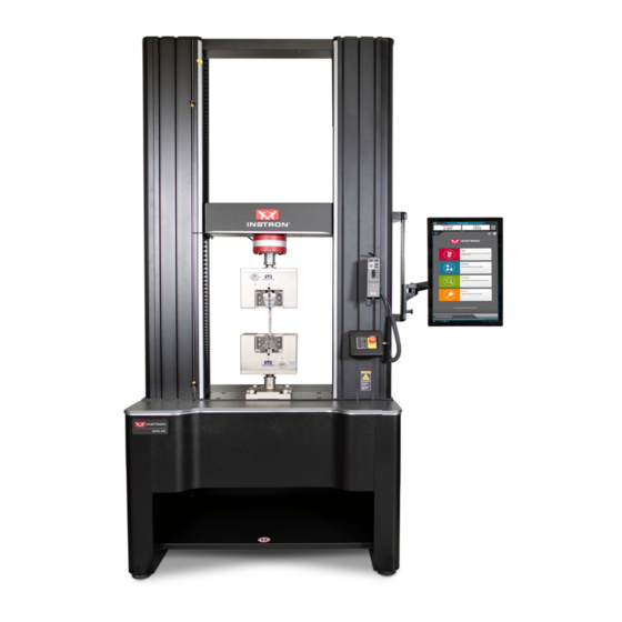
Chapter: Introduction System Description and Terminology ® Figure 1. 68FM-100 Floor Model with Bluehill Operator Dashboard - Front View M10-17543-EN... - Page 15 System Description and Terminology Legend for Figure 1 Label Component T-slots Top plate Column cover Load cell Upper limit switch Limit switch actuator Lower limit switch Emergency stop button Indicator panel ® Bluehill Operator Dashboard (optional) Handset Product Support: www.instron.com...
- Page 16 Chapter: Introduction ® Figure 2. 68FM-100 Floor Model with Bluehill Operator Dashboard - Rear View M10-17543-EN...
-
Page 17: Components
® contacting extensometer. Contact your regional Instron office or check our web site at www.instron.com for assistance with Instron’s grips and fixtures. The following table defines the components of the testing system: Product Support: www.instron.com... -
Page 18: Principle Of Operation
The load cell converts this load into an electrical signal that the software measures and displays. ® ® Bluehill Instron Software testing software that controls the testing system, running tests and analyzing test data to produce test results. Specimen A single piece of material to be tested. -
Page 19: Software
Handset - holds all the controls for the testing system. Software ® Control of the testing system is carried out via Instron Bluehill software. Setting test parameters, operating the system, and collecting test data is done through the software program. - Page 20 Chapter: Introduction Table 3. Safety and Information Labeling Descriptions Label Meaning Purpose Electrical Indicates that an electrical hazard exists hazard from high voltage and/or electrical current. Disconnect power Disconnect the power supply before supply servicing machine. Electrical - fuse warning Indicates an electrical hazard exists.
-
Page 21: Product Support
For advice on the disposal of electrical and electronic equipment in your country, contact your local Instron representative. Product Support ® Instron provides documentation, including manuals and online help, that can answer many of the questions you may have. -
Page 22: Product Documentation
If you cannot find answers in these sources, contact Instron Service directly. A list of ® Instron offices is available on our website at www.instron.com. In the US and Canada, you can call directly at 1-800-473-7838. Product Documentation ® Instron offers a comprehensive range of documentation to help you get the most out of your Instron products. -
Page 23: Chapter 2: Requirements
Environmental specifications ......... 29 • 68FM-100 Power Requirements and Cords ......31 •... -
Page 24: Supplier's Responsibilities
Under Instron’s standard contract, the shipping terms are Ex-Works (or FOB Factory), meaning ownership and liability for the testing system transfers to the customer at Instron’s loading dock. Unless other shipping terms are specified in a purchase order, which Instron does not dispute, the Ex-Works shipping terms apply. Under these terms, the customer is responsible for securing the applicable transit insurance on the shipment and arranging safe transport to the final destination. - Page 25 Instron’s loading dock. Unless other shipping terms are specified in a purchase order, which Instron does not dispute, the Ex-Works shipping terms apply. Under these terms, Instron is responsible for insurance cover while the testing system is in the factory up until it reaches the loading dock for shipping.
-
Page 26: Site Requirements
Chapter: Requirements Site requirements Proper site preparation is imperative so that the testing system operates in accordance with its specifications. Frame location The load frame must not be located against a wall or other object that interferes with air ventilation around the frame. Proper air ventilation is required to dissipate the heat generated from the frame base. -
Page 27: Power Supply
Our goal is to provide remote diagnostics in order to resolve system issues. ® Having a network drop or digital phone line available will enable an Instron service representative to connect to the testing system to diagnose and resolve problems more efficiently. -
Page 28: Ceiling Clearance
® ® Instron Service or your local Instron office for advice. Dry compressed air A dry, compressed air supply regulated to a maximum pressure of 8.3 bar (120 psi) is required for the integrated air kit. -
Page 29: Environmental Specifications
IP 2X. Protective measures may be required if excessive dust, corrosive fumes, Rating electromagnetic fields or hazardous conditions are encountered. Conformity with EU directives ® Instron declares under our sole responsibility that 68FM testing systems are in conformity with all relevant provisions of the following regulations: • Machinery Directive 2006/42/EC •... -
Page 30: Environmental Impact
The noise output from equipment used for materials or structures testing is also depen- dent upon the items under test. Instron recommends that users carry out their own noise level measurements to ensure the continuous safety and comfort of personnel. -
Page 31: 68Fm-100 Power Requirements And Cords
4.5 (14.75) 4.5 (14.75) 1. Voltages are measured phase-to-phase. They are NOT measured between phase and ground or neutral. Table 6. 68FM-100 power requirements - single phase option Parameter Specification Maximum Power (VA) 3000 Single Phase Voltage (Vac) (-5% / +10%) - Page 32 Chapter: Requirements Figure 4 on page shows the Wye 3-phase configuration and Figure 5 on page shows the Delta 3-phase configuration. The 3-phase configuration uses a 4-wire connection as follows: • (L1) Line 1/Phase A • (L2) Line 2/Phase B •...
-
Page 33: Power Cord Selections
Instron chooses the cord according to the customary voltage that matches the shipping destination for the system. Instron provides the appropriate male plug, as shown in the following tables. It is the customer’s responsibility to provide the appropriate female receptacle for the plug. - Page 34 Chapter: Requirements Table 7. Shipping destination in North America Voltage and Phase Plug supplied 208/240 3-phase NEMA L15-20P (250V, 20A, 4-wire) 208/240 single phase NEMA L6-20P (250V, 20A, 3-wire) Table 8. Shipping destination outside North America Voltage and Phase Plug supplied 208/240 3-phase IEC 60309 (blue, 250V, 16A, 4-wire, 3P+E) M10-17543-EN...
-
Page 35: Checklist For Site Preparation
Instron Service or your local Instron office for assistance. Not all computers are compatible with Instron testing systems. If you intend to purchase ® a computer from an outside vendor, contact Instron Service to verify its compatibility. -
Page 36: Transporting
Pathway from the loading dock to the final site location has sufficient width and height to fit the frame and forklift (or crane). Measure all doors and hallways. Refer to “68FM-100 Dimensions and Weight” on page for dimensions and weights of the testing system without its packaging. Refer to “68FM-100... -
Page 37: Scheduling Installation
When the testing site is ready, and the frame has been moved to its final operating ® location, contact Instron to schedule an installation appointment. ® A list of Instron offices is available on our website at www.instron.com. In the United States and Canada, you can call 1-800-473-7838. Product Support: www.instron.com... - Page 38 Chapter: Requirements M10-17543-EN...
-
Page 39: Chapter 3: Specifications
68FM-100 Dimensions and Weight ........ - Page 40 Chapter: Specifications Table 10. 68FM-100 dimensions - standard height Letter Designation Description Dimension - mm (inch) Overall height - Standard base 2287 (90) Overall height - Tall base 2587 (102) Maximum vertical test space (test daylight - from 1494 (58.8)
- Page 41 68FM-100 Dimensions and Weight Table 12. Dimension “C” - crosshead to load cell clevis pin hole Load cell capacity Connection type Distance - mm (inch) 100 kN 110 (4.33) Product Support: www.instron.com...
- Page 42 Chapter: Specifications Figure 6. 68FM-100 frame dimensions - front view M10-17543-EN...
- Page 43 68FM-100 Dimensions and Weight Figure 7. 68FM-100 frame dimensions - side view * 3-phase power (3P) requires 158 mm (6.2 in) and single phase power (1P) requires 142 mm (5.6 in) space behind the frame to accommodate the power cable bend radius.
- Page 44 Chapter: Specifications Figure 8. 68FM-100 frame dimensions - rear view M10-17543-EN...
-
Page 45: Frame Stabilizers
68FM-100 Dimensions and Weight 1486 1638 1604 Figure 9. 68FM-100 frame dimensions - including dashboard Frame stabilizers Frame stabilizers are available as an option on all frames. They are always provided on extra height frames with the tall base option. Warning Do not remove the stabilizer bars at any time during the unpacking, lifting and handling of the frame. - Page 46 Chapter: Specifications 1048 Figure 10. Dimensions with frame stabilizers - front view M10-17543-EN...
-
Page 47: System Weight
68FM-100 Dimensions and Weight 1090 Figure 11. Dimensions with frame stabilizers - side view System weight The following tables list the weight of each frame configuration and the corresponding maximum allowable weight of accessories (e.g. grips and testing fixtures) for that configuration. -
Page 48: Accessory Mounting Dimensions
Chapter: Specifications Table 14. System weight - extra height Maximum allowable weight of accessories Base height Frame weight kg (lb) kg (lb) Standard 860.9 (1898) 823.5 (1815) Tall 1013.6 (2235)* 719.9 (1587) ® The frame weight value does not include additional accessories such as the Bluehill Operator Dashboard or any load cell. -
Page 49: Base Beam Dimensions
45±0.4 45±0.4 75±0.4 6X 60° M16X2.0 - 6H 30±0.5 M10X1.5 - 6H 25±0.5 Figure 12. View of base beam from above 60.05 60.00 11.1±0.5 57±0.15 M48X2.0 LH Figure 13. View of cross section G-G of frame base Product Support: www.instron.com... -
Page 50: Crosshead Dimensions
Chapter: Specifications Crosshead dimensions 10X M10X1.5 - 6H 25 0.5 45±0.4 45±0.4 100±0.15 PCD Figure 14. View of underside of crosshead 10X M10X1.5 - 6H 25±0.5 6X 60° 30° 6X 60° 45±0.4 45±0.4 M16X2.0 - 6H 40±0.5 11.1±0.5 THRU ALL 17.4±0.5 11.0±0.5 100±0.15 PCD... -
Page 51: Top Plate Dimensions
3.00 5±0.15 60.05 40.05 60.00 37±0.15 57±0.15 40.00 5±0.15 32±0.25 3.12 3.00 Figure 16. View of cross section H-H of crosshead Top plate dimensions 4X M10X1.5 THRU 280±0.15 90±0.15 Figure 17. View of underside of top plate Product Support: www.instron.com... -
Page 52: System Performance
3-phase electrical configuration. Table 17 on page lists those performance parameters that differ for the single- phase electrical configuration. Table 16. 68FM-100 system performance Parameter Specifications Testing type Tension, compression, and through zero operation. Basic control mode... - Page 53 Maximum speed - mm/min (in/min) 1016 (40) Minimum speed - mm/min (in/min) 0.0001 (0.000004) Maximum force at full speed - kN (lbf) 50 (11240) Maximum speed at full force - mm/min (in/min) 508 (20) Return speed - mm/min (in/min) 1016 (40) Product Support: www.instron.com...
- Page 54 Chapter: Specifications M10-17543-EN...
-
Page 55: Chapter 4: Risk Reduction And Safe Use
• the jog, return and test speeds used • the type of specimen being tested • the size of the specimen being tested • the design of grips and test fixtures Product Support: www.instron.com... -
Page 56: Rapid Crosshead Motion
Chapter: Risk reduction and safe use • the experience of the operator using the equipment It is our strong recommendation, therefore, that you carry out your own risk assessment for your particular equipment setup and testing application. Each of the following sections describes a specific hazard zone of the testing system and lists the most common risks for testing using this equipment. - Page 57 Use a specimen insertion tool to keep fingers out of the space between the fixtures. • Use an interlocked shield to limit or disallow motion when the shield door is open. When the space is less than 25mm, the crush hazard is very significant, so this is the best option. Product Support: www.instron.com...
-
Page 58: Pinching Fingers Between Grip Jaw Faces
Chapter: Risk reduction and safe use Pinching fingers between grip jaw faces Warning Pinch hazard to fingers. This hazard relates to grip jaws closing quickly, pinching fingers. Recommendations For 2712 Series pneumatic grips: • In the documentation supplied with the grips, read and follow the safety recommendations for installing a specimen. -
Page 59: Impact Of Debris From Breaking Specimens
Hazard from flying debris. This hazard relates to brittle or composite specimens that can explode when they break. Recommendations For less dangerous debris (specimen dust or fibers, for example): • Use personal protection equipment (for example safety glasses). Product Support: www.instron.com... -
Page 60: Collision Mitigation
Chapter: Risk reduction and safe use For more dangerous projectile debris (brittle composite specimens, for example): • Use an interlocked shield. Collision Mitigation The 3400 and 6800 Series systems are equipped with the Collision Mitigation feature to help reduce accidental equipment and specimen damage. Collision Mitigation enables the system to continually monitor force during jog and return operations, and will automatically stop the crosshead movement if an unexpected force is detected. -
Page 61: Ingress Protection
Clean the testing system and adjacent areas frequently with a vacuum or soft brush to prevent any accumulation of debris. • ® As part of periodic maintenance, contact Instron Service to inspect the inside of the testing system for accumulation of debris, and clean it if necessary. •... -
Page 62: Operator Protection Overview
(if present) and any installed accessories. ® 3. If you have reason to believe that liquid entered the testing system, contact Instron Service. The service engineer will remove the covers of the equipment and clean up all traces of spilled liquid. - Page 63 Operator Protection lets an Administrator configure the testing system to be consistent with the risk assessment for that system. Access to the controls for Operator Protection is password protected. If you have ® Administrator rights you can modify Operator Protection in the Admin tab in Bluehill Product Support: www.instron.com...
- Page 64 Chapter: Risk reduction and safe use M10-17543-EN...
-
Page 65: Chapter 5: Lifting And Handling
General handling precautions ........65 • 68FM-100 Packaging dimensions and weight ......66 •... -
Page 66: 68Fm-100 Packaging Dimensions And Weight
68FM-100 Packaging dimensions and weight Instron recommends leaving the load frame in its packaging while moving it to its final site location within your building. Use the information in... -
Page 67: Right The Frame From A Prone Position
4. Use the packing list to inventory all the boxed items. Some accessories may be in the container with the load frame or may be packaged separately. Do not open any of the packing boxes until the Instron service engineer arrives to install your testing system. The packing list indicates the total number of boxes that are included in the shipment. -
Page 68: Before You Begin
Chapter: Lifting and handling The recommended procedure is to lift from both the crosshead and from hoist bolts in the base beam. For this procedure you will need: • Two cranes with a combined load rating that is appropriate for the load frame’s gross weight, including the weight of any installed accessories. -
Page 69: Procedure
3. Install two M16 hoist bolts into the frame base and attach two additional slings to the bolts, as shown in Figure 18 on page 70. Product Support: www.instron.com... - Page 70 Chapter: Lifting and handling Figure 18. Righting a Load Frame Using a Crane Legend for Figure 18 Label Description Two slings around the crosshead. Two slings attached to two M16 hoist rings screwed into frame base beam. 4. Slowly lift the frame until the weight of the frame is fully supported by the slings. 5.
- Page 71 10. Remove the slings from the crosshead. 11. Remove the slings and M16 hoist bolts from the frame base. The frame can now be positioned into its operating location and then installed by an Instron service representative. Product Support: www.instron.com...
-
Page 72: Transport Floor Model Frames
Chapter: Lifting and handling Transport floor model frames ® Instron strongly recommends using professional riggers experienced in moving heavy equipment. The only approved method for lifting the frame is to use a forklift with padded forks to lift the load frame from under the crosshead. Do not attempt to lift the frame at any other... - Page 73 Hazard - Do not tilt an unsupported load frame more than 10° when it is in the upright position. Tilting by more than 10° may topple the load frame and cause personal injury and equipment damage. 10° 10° Figure 21. Maximum tilt angle Product Support: www.instron.com...
-
Page 74: Before You Begin
• The frame and forklift can fit through all doorways, halls, elevators or stairs from the shipping dock to its final site location. Check the dimensions for your frame model (“68FM-100 Dimensions and Weight” on page 39). • The floors from the shipping dock to the final site location have sufficient support for the weight of the load frame and forklift combined. -
Page 75: Lift The Frame By The Crosshead
Use this procedure to move the frame to its final location, after it has been righted from the prone position. This method requires protective padding on either the crosshead or forklift arms to protect the crosshead from scratching or marring. Figure 22. Lifting the Frame from the Crosshead Product Support: www.instron.com... - Page 76 3. Move the frame to its operating location. 4. Place the load frame carefully into position. 5. Remove the padded forks from under the frame’s crosshead. ® When the frame is in its operating location, Instron Service can proceed to install your new testing system. M10-17543-EN...
-
Page 77: Index
......23 Instron......24 routine maintenance. - Page 78 M10-17543-EN...
- Page 80 www.instron.com...
Need help?
Do you have a question about the 68FM-100 and is the answer not in the manual?
Questions and answers