Table of Contents
Advertisement
Quick Links
This user guide describes the TLV840EVM evaluation module (EVM). This guide contains the EVM
schematic, bill of materials (BOM), assembly drawing, and top and bottom board layouts.
...................................................................................................................
1
1.1
1.2
2
2.1
2.2
2.3
3
3.1
3.2
4
4.1
Input Power (V
4.2
4.3
4.4
Reset Time Delay Programming (Program t
1
2
3
TLV840EVM Schematic
4
5
6
7
.....................................................................................................................
8
9
10
11
12
13
14
15
TLV840EVM RESET Delay Time (t
16
TLV840EVM RESET Delay Time (t
..........................................................................................................................
1
....................................................................................................................
2
3
4
SNVU704 - February 2020
Submit Documentation Feedback
TLV840EVM Voltage Supervisor User Guide
............................................................................................
...............................................................................................
.................................................................................
............................................................................................
......................................................................................
.............................................................................................................
....................................................................................................
.......................................................................................................
...............................................................................................
..................................................................................................
)
DD
......................................................................................
...........................................................................................
....................................................................................................
.................................................................................................
....................................................................................................
..................................................................................
..................................................................................................................
..............................................................................................................
.................................................................................................................
.............................................................................................................
.............................................................................................
) with C
D
) with C
D
) with C
D
...................................................................................................
Copyright © 2020, Texas Instruments Incorporated
Contents
...............................................................................
........................................................
via CT)
D
List of Figures
..............................................................................
...............................................................
.............................................
Floating
T
Tied to GND Through 0.1-µF Capacitor
T
Tied to GND Through 0.01-µF Capacitor
T
................................................................
Floating
T
List of Tables
......................................................................
TLV840EVM Voltage Supervisor User Guide
User's Guide
SNVU704 - February 2020
3
4
4
4
5
6
7
9
9
9
10
10
10
11
11
3
4
5
7
7
7
7
7
7
8
10
10
10
...........................
12
.........................
12
12
6
9
9
10
1
Advertisement
Table of Contents

Related Manuals for Texas Instruments TLV840EVM


Summary of Contents for Texas Instruments TLV840EVM
-
Page 1: Table Of Contents
User's Guide SNVU704 – February 2020 TLV840EVM Voltage Supervisor User Guide This user guide describes the TLV840EVM evaluation module (EVM). This guide contains the EVM schematic, bill of materials (BOM), assembly drawing, and top and bottom board layouts. Contents ........................ - Page 2 Trademarks All trademarks are the property of their respective owners. TLV840EVM Voltage Supervisor User Guide SNVU704 – February 2020 Submit Documentation Feedback Copyright © 2020, Texas Instruments Incorporated...
-
Page 3: Introduction
Introduction The TLV840EVM is an evaluation module (EVM) for the TLV840 voltage supervisor. The TLV840EVM can be used with any TLV840 device variant but note that if using the push-pull variants (TLV840PLXX or TLV840PHXX), the shunt on J2 must be removed as push-pull devices do not use a pull-up resistor so R1 must be disconnected. -
Page 4: Related Documentation
Data Center and Enterprise Computing • Multifunction Printer Schematic, Bill of Materials, and Layout This section provides a detailed description of the TLV840EVM schematic, bill of materials (BOM), and layout. TLV840EVM Voltage Supervisor User Guide SNVU704 – February 2020 Submit Documentation Feedback... -
Page 5: Tlv840Evm Schematic
Schematic, Bill of Materials, and Layout www.ti.com TLV840EVM Schematic Figure 3. TLV840EVM Schematic SNVU704 – February 2020 TLV840EVM Voltage Supervisor User Guide Submit Documentation Feedback Copyright © 2020, Texas Instruments Incorporated... -
Page 6: Tlv840Evm Bill Of Materials
Adjustable Reset Time Delay and Manual Reset Option FID1, FID2, FID3 Fiducial mark. There is nothing Fiducial to buy or mount. TLV840EVM Voltage Supervisor User Guide SNVU704 – February 2020 Submit Documentation Feedback Copyright © 2020, Texas Instruments Incorporated... -
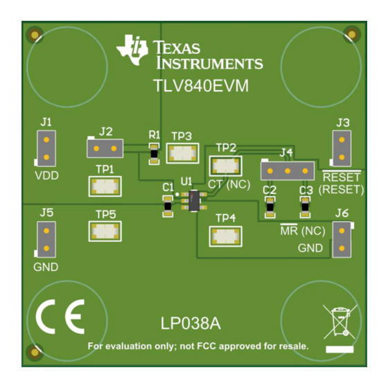
Page 7: Layout And Component Placement
EVM. Figure 4. Component Placement—Top Assembly Figure 5. Component Placement—Bottom Assembly Figure 6. Layout—Top Figure 7. Layout—Bottom SNVU704 – February 2020 TLV840EVM Voltage Supervisor User Guide Submit Documentation Feedback Copyright © 2020, Texas Instruments Incorporated... -
Page 8: Top Layer
Schematic, Bill of Materials, and Layout www.ti.com Figure 8. Top Layer Figure 9. Bottom Layer Figure 10. Top Solder Mask TLV840EVM Voltage Supervisor User Guide SNVU704 – February 2020 Submit Documentation Feedback Copyright © 2020, Texas Instruments Incorporated... -
Page 9: Evm Connectors
Connection to GND pin. Allows user to connect to the ground plane. EVM Jumpers Table 3 lists the jumpers on the TLV840EVM. As ordered, the EVM will have five jumpers installed. Table 3. List of Onboard Jumpers JUMPER DEFAULT DESCRIPTION CONNECTION Both pins on J1 are connected together. -
Page 10: Evm Setup And Operation
EVM Setup and Operation www.ti.com EVM Setup and Operation This section describes the functionality and operation of the TLV840EVM. The user must read the TLV840 datasheet for electrical characteristics of the device. Input Power (V The VDD supply is connected through the J1 header on board. Both pins of jumper J1 are connected together so power can be applied to either pin. -
Page 11: Reset Output (Reset)
Figure 13. TLV840EVM Glitch Immunity Reset Output (RESET) The TLV840EVM comes populated with TLV840MADL29 device variant which has open-drain, active-low output topology for the RESET pin. The other device variants provide different output topolgies and can be used on this EVM. Note: if using a TLV840 device variant with push-pull output topology, the pull-up resistor must be disconnected by leaving jumper J2 open. -
Page 12: Tlv840Evm Reset Delay Time
)= 56.8 ms Reset Delay (t )= 5.42 ms RESET RESET Figure 14. TLV840EVM RESET Delay Time (t ) with C Figure 15. TLV840EVM RESET Delay Time (t ) with C Tied to GND Through 0.1-µF Capacitor Tied to GND Through 0.01-µF Capacitor Reset Delay (t )= 57.6 µs... - Page 13 TI products. TI’s provision of these resources does not expand or otherwise alter TI’s applicable warranties or warranty disclaimers for TI products. TI objects to and rejects any additional or different terms you may have proposed. IMPORTANT NOTICE Mailing Address: Texas Instruments, Post Office Box 655303, Dallas, Texas 75265 Copyright © 2022, Texas Instruments Incorporated...
Need help?
Do you have a question about the TLV840EVM and is the answer not in the manual?
Questions and answers