Table of Contents
Advertisement
Advertisement
Table of Contents

Subscribe to Our Youtube Channel
Related Manuals for Faro FOCUS


Summary of Contents for Faro FOCUS
- Page 1 FOCUS® Laser Scanner Accessories Manual May 2021 ...
-
Page 2: Legal Notices
® FARO FOCUS® Laser Scanner Accessories Manual Legal Notices Legal Notices Release Notice No part of this publication may be reproduced, or transmitted in any form or by any means without written permission of FARO Technologies, Inc. FARO TECHNOLOGIES, INC. MAKES NO WARRANTY, EITHER EXPRESS OR IMPLIED, INCLUDING BUT NOT LIMITED TO ANY IMPLIED WARRANTIES OF MERCHANTABILITY OR FITNESS FOR A PARTICULAR PURPOSE, REGARDING THE FARO SCENE, FARO FOCUS LASER SCANNER AND ANY MATERIALS, AND MAKES SUCH MATERIALS AVAILABLE SOLELY ON AN “AS-IS” BASIS. IN NO EVENT SHALL FARO TECHNOLOGIES INC. BE LIABLE TO ANYONE FOR SPECIAL, COLLATERAL, INCIDENTAL, OR CONSEQUENTIAL DAMAGES IN CONNECTION WITH OR ARISING OUT OF THE PURCHASE OR USE OF THE FARO SCENE, FARO FOCUS LASER SCANNER OR THEIR MATERIALS. THE SOLE AND EXCLUSIVE LIABILITY TO FARO TECHNOLOGIES, INC., REGARDLESS OF THE FORM OF ACTION, SHALL NOT EXCEED THE PURCHASE PRICE OF THE MATERIALS DESCRIBED HEREIN. THE INFORMATION CONTAINED IN THIS MANUAL IS SUBJECT TO CHANGE WITHOUT NOTICE AND DOES NOT REPRESENT A COMMITMENT ON THE PART OF FARO TECHNOLOGIES INC. ACCEPTANCE OF THIS DOCUMENT BY THE CUSTOMER CONSTITUTES ACKNOWLEDGMENT THAT IF ANY INCONSISTENCY EXISTS BETWEEN THE ENGLISH AND NON-ENGLISH VERSIONS, THE ENGLISH VERSION TAKES PRECEDENCE. Copyright Notice © Copyright 2010 - 2021 FARO Technologies Inc.. This product includes third-party and open source resources. For license and copyright information pertaining to the use of these resources, refer to the following document in the FARO Knowledge Base: https://knowledge.faro.com/Essentials/General/3rd-Party_Open_Source_License_Information_for_FARO_ Products FARO FOCUS® LASER SCANNER (00.00) -
Page 3: Disposal
® FARO FOCUS® Laser Scanner Accessories Manual Disposal Disposal At the end of an electronics product's lifecycle, the product cannot disposed along with normal waste. Take electronic products to recycling facilities that accept electronic devices. Contact your local government or local waste disposal operators to comply with local laws. FARO FOCUS® LASER SCANNER (00.00) Page 3 of 36... -
Page 4: Table Of Contents
® FARO FOCUS® Laser Scanner Accessories Manual Table of Contents Table of Contents Legal Notices Copyright Notice Disposal Table of Contents Chapter 1: Introduction About Laser Scanner Accessories Accessory Compatibility Notes and Signs Chapter 2: Status Indicator Status Indicator Overview Inserting the status indicator Removing the status indicator Chapter 3: Thermal Protection Covers Thermal Protection Covers Overview Preparing the thermal protection covers Storing and transporting the thermal protective covers... - Page 5 ® FARO FOCUS® Laser Scanner Accessories Manual Table of Contents PanoCam Overview PanoCam Requirements PanoCam Mount Setup Attach the Camera/Mounting Bracket Assembly to the Scanner Removing the PanoCam Mount From the Scanner Enabling the PanoCam in the Controller Software PanoCam Calibration PanoCam Scanning Expediting the Scanning Process PanoCam Example Images Importing a PanoCam Project into SCENE Managing Occlusions Occlusion Examples FARO FOCUS® LASER SCANNER (00.00) Page 5 of 36...
-
Page 6: Chapter 1: Introduction
® FARO FOCUS® Laser Scanner Accessories Manual Chapter 1: Introduction Chapter 1: Introduction About Laser Scanner Accessories This document provides information about the accessories that are available for your FARO Focus Laser Scanner. To order these accessories, contact your regional FARO Sales Representative. The following accessories are available: Status Use the status indicator when you want to see the scanner’s LED colors and blink codes Indicator on from more positions and from a greater distance. Part number: ACCSS8048. page 9 Thermal Use the thermal protection covers when you want to operate the scanner in direct sun or at Protection temperatures in the range 40° C to 55° C (104° F to 131° F). Part numbers: ACCSS8014 Covers on non-display side of scanner. ACCSS8049 display side of scanner. page 13 Use the FARO PanoCam mount to attach a panoramic camera to the FOCUS® LASER PanoCam on SCANNER The PanoCam system expedites the scanning processing by capturing colorized page 21 photos. Automation Automation accessories help you automate the scanner, merge your data with scan data, and Accessories ... -
Page 7: Notes And Signs
® FARO FOCUS® Laser Scanner Accessories Manual Chapter 1: Introduction Focus and Plus Focus Focus and Plus Focus Focus Focus Focus 350A 150A PanoCam Mount Notes and Signs The following visual conventions are used throughout the documentation. DANGER: A DANGER notice denotes a hazard. It calls attention to an operating procedure or practice that, if not correctly performed or adhered to, will result in personal injury or death. Do not proceed beyond a DANGER notice until the indicated conditions are fully understood and met. WARNING: A WARNING notice denotes a hazard. It calls attention to an operating procedure or ... - Page 8 ® FARO FOCUS® Laser Scanner Accessories Manual Chapter 1: Introduction FARO FOCUS® LASER SCANNER (00.00) Page 8 of 36...
-
Page 9: Chapter 2: Status Indicator
® FARO FOCUS® Laser Scanner Accessories Manual Chapter 2: Status Indicator Chapter 2: Status Indicator Status Indicator Overview The status indicator enables you to see the scanner’s LED colors and blink codes from more positions and from a greater distance. The scanner’s LED indicator is switched off when the status indicator is installed. The status indicator is suitable for indoor or outdoor use. The light of the status indicator is visible from all sides of the scanner except the side with the touch screen. The status indicator can function no matter the orientation of the scanner—even if it is upside-down. Figure 2-1 : Status Indicator NOTICE: The status indicator is not waterproof. Do not use the indicator in the rain, or where water could drip onto it. Inserting the status indicator The scanner should not be stored with the status indicator inserted into the accessory bay, so you will need to insert it before using the scanner and remove it before storing the scanner. 1. Check the gold plated contact pins of the status indicator before inserting it into the accessory bay. Clean with a dry cotton swab if necessary. 2. Ensure that the laser scanner is switched off. - Page 10 ® FARO FOCUS® Laser Scanner Accessories Manual Chapter 2: Status Indicator a. The cover is removed by pressing down on one side of the cover (indicated by !), which causes the other side to pop up. b. Grasp the side that is now elevated from both sides and pull the cover completely out of the bay. c. Retain the protective cover. Figure 2-2 : Accessory bay for the status indicator with covers 4. Insert the status indicator into the accessory bay. The correct bay is colored red. Figure 2-3 : Accessory bay for the status indicator with covers removed NOTICE: Do not insert the status indicator into the accessory bay on the left side of the scanner. Forcing ...
-
Page 11: Removing The Status Indicator
® FARO FOCUS® Laser Scanner Accessories Manual Chapter 2: Status Indicator LED state Scanner state Orange An error or warning has occurred Orange flashing quickly Low battery or error during boot or shutdown Red flashing Scan operation with laser on Removing the status indicator Remove the status indicator before placing the laser scanner in its case. 1. Switch off the scanner. 2. Remove the status indicator by grasping it with two fingers on the corners shown in Figure 2-4 and pulling vertically. Figure 2-5 : Do not pull here Figure 2-4 : Pull here to remove 3. Replace the accessory bay cover after removing the status indicator. - Page 12 ® FARO FOCUS® Laser Scanner Accessories Manual Chapter 2: Status Indicator FARO FOCUS® LASER SCANNER (00.00) Page 12 of 36...
-
Page 13: Chapter 3: Thermal Protection Covers
FOCUS® Laser Scanner Accessories Manual Chapter 3: Thermal Protection Covers Chapter 3: Thermal Protection Covers Thermal Protection Covers Overview FARO laser scanners are normally able to operate at ambient temperatures from 5 °C to 40 °C (4 °F to 104 °F). The thermal protection covers make it possible to operate the scanner in temperatures between 40 °C and 55 °C (104 °F to 131 °F) and in strong direct sunlight. The covers provide: • shielding against IR radiation • high-performance thermal insulation to prevent excess heat intrusion • latent-heat absorbers to remove excess heat from the device Figure 3-1 : FARO thermal protection covers FARO FOCUS® LASER SCANNER (00.00) Page 13 of 36... -
Page 14: Preparing The Thermal Protection Covers
® FARO FOCUS® Laser Scanner Accessories Manual Chapter 3: Thermal Protection Covers Preparing the thermal protection covers The covers must be pre-cooled inside a conventional freezer before each use. We recommend a freezer that can bring the temperature of the covers down to less than -15 °C (5 °F). Depending on the initial temperature of the covers, this process can take up to 6 hours. NOTE: For maximum flexibility, we recommend having a second pre-cooled set of covers at hand. This allows quick on-site replacement of covers during operation and provides optimum long-term performance. Storing and transporting the thermal protective covers During transport to the scanning site, the covers need to be kept cold (optimum: -15 °C (5 °F)) by transporting them in a high-quality cooler equipped with ice packs or with active refrigeration. Figure 3-2 : Set of pre-cooled thermal insulation covers inside an insulated cooler Transporting the scanner to working site... -
Page 15: Preparing The Scanner Hardware
® FARO FOCUS® Laser Scanner Accessories Manual Chapter 3: Thermal Protection Covers Preparing the scanner hardware • Ensure that the Power Block is completely charged. We recommend to have at least 2 fully-charged Power Blocks for scanning in extreme conditions. • Set all scanning parameters prior to working with the scanner on-site. (E.g., scan project folders, file naming, user settings, etc.; scan resolution and quality, color settings, scan profile, detector settings, etc.) This will minimize the amount of time that the scanner will be exposed to the environment. Setting up on-site and scanning operation in hot ambient conditions This section provides details about how to set up the scanner with the cover. Set up the tripod at the desired scan position following all recommendations in the scanner manual. Insert a fully-charged power pack into the battery slot of the scanner. If a status indicator is present in the scanner, it should be removed while the scanner is switched off. Start the scanner and recall all desired scan / project settings. After this step, the scanner should be in status Ready for measurement. If a status ... - Page 16 ® FARO FOCUS® Laser Scanner Accessories Manual Chapter 3: Thermal Protection Covers Figure 3-3 : Loosen Velcro straps Figure 3-4 : Display-side thermal cover 3. Hold a cover on both sides, and gently slide it over the scanner housing. Repeat this step with the second cover on the other side of the laser scanner housing. Figure 3-5 : Slide thermal protection cover onto scanner 4. Tighten and fix the two Velcro straps at the bottom of each cover so the cover fits ...
-
Page 17: Accessing The Laser Scanner With The Thermal Protection Cover Installed
® FARO FOCUS® Laser Scanner Accessories Manual Chapter 3: Thermal Protection Covers 5. After installation, recheck the position of the cover. Ensure that the inner rim line of the cover is aligned parallel to the inner edge of the scanner chassis, with an offset of 3 to 4 mm. The scanner chassis should be visible from all sides. Figure 3-7 : Case fixed correctly After installing both the covers, the laser scanner is now ready for operation. Accessing the laser scanner with the thermal protection cover installed As long as the FARO Laser Scanner is exposed to hot climate conditions or intense direct sunlight with temperatures greater than 40 °C, it is highly recommended to leave the cover installed over the full working period or series of scanning measurements. But if you need to access the scanner, the cover front faces can be separately opened to access the display panel or power pack and SD card slot. To open a single front face of the cover, pull the vertical Velcro flaps away from the device and lift the front face. For free access to the scanner in standby mode, the opened front face can also be flipped over to the top of the scanner. Figure 3-8 : Opening the cover ... -
Page 18: Maintaining The Focus Scanner And Thermal Protective Cover On-Site
® FARO FOCUS® Laser Scanner Accessories Manual Chapter 3: Thermal Protection Covers Figure 3-10 : Access to Power Pack and Figure 3-9 : Access to Display Battery To close the front face, wrap and press both Velcro-based flaps towards the sides of the cover. Re-check the cover alignment. Maintaining the Focus scanner and thermal protective cover on-site When exposed to temperatures of 40 °C (104 °F) or greater, the Focus laser scanner will gradually warm up during continuous operation, even if when using the thermal protection cover as described in the preceding sections. As a consequence, repetitive scan operation under such conditions will be limited in time up to a point where the internal temperature control of the FARO Laser Scanner sends a critical temperature warning message (plus acoustic signal) to the user. At this point, the scanner must be switched off and cooled down, preferably to the temperature range 20 °C to 25 °C (68 °F to 77 °F), to re-establish the recommended conditions for continuation of scanning operation. Also the cover should be replaced at this point. FARO FOCUS® LASER SCANNER (00.00) -
Page 19: Chapter 4: Automation Accessories
® FARO FOCUS® Laser Scanner Accessories Manual Chapter 4: Automation Accessories Chapter 4: Automation Accessories Use these accessories to help you automate the scanner, merge your data with scan data, and operate the scanner in helical mode. The automation accessories are not described in this document. You can learn about them and about automation strategies in the Automation Interface Manual. • Automation Adapter (Part number: ACCSS8004.) A mechanical base that provides an Ethernet and automation connection to the scanner • Helical Adapter Upgrade (Part number: ACCSS8015.) A bracket that prevents the scanner from rotating so that it can be used in helical mode. • Automation Test Box (Part number: ACCSS8027.) Test controller to verify the proper function of the Automation Adapter’s automation socket. • Zero Point Clamp (Part number: ACCSS6037.) A mounting bracket that enables quick and ... - Page 20 ® FARO FOCUS® Laser Scanner Accessories Manual Chapter 4: Automation Accessories FARO FOCUS® LASER SCANNER (00.00) Page 20 of 36...
-
Page 21: Chapter 5: Panocam
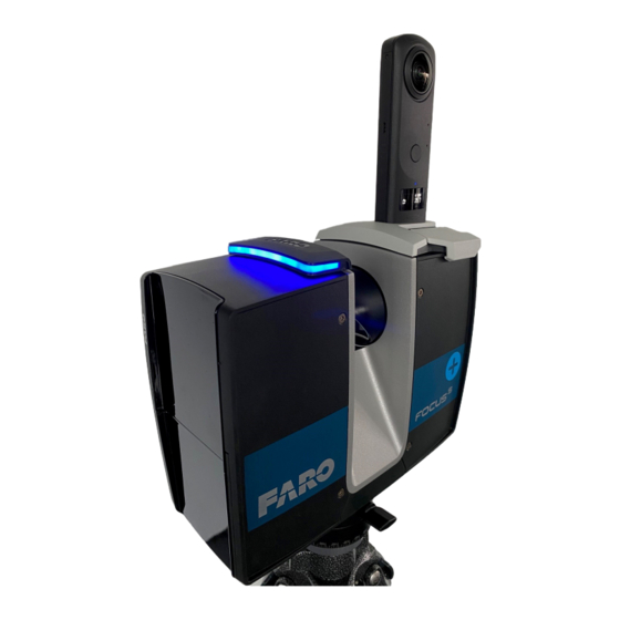
® FARO FOCUS® Laser Scanner Accessories Manual Chapter 5: PanoCam Chapter 5: PanoCam PanoCam Overview Use the FARO PanoCam mount to attach a panoramic camera to the FOCUS® LASER SCANNER. The PanoCam system expedites the scanning process by capturing colorized photos. PanoCam Requirements A Focus S/S Plus laser scanner with firmware 6.8.0, or newer. SCENE 2021.0 or later Ricoh Theta Z1 camera FARO PanoCam mounting bracket 3mm Hex Key (included) PanoCam Mount Setup The first part of the hardware setup requires attaching the panoramic camera to the F ARO PanoCam mounting bracket. You will need: Ricoh Theta Z1 camera FARO PanoCam mounting bracket 3mm Hex Key (included) FARO FOCUS®... - Page 22 ® FARO FOCUS® Laser Scanner Accessories Manual Chapter 5: PanoCam Connect the camera's USB-C connector to the USB connector on the mount. Use the hex-key to tighten the camera screw, which is located on the bottom of the mount. " CAUTION: Do not over-tighten the screw. Damage to the camera or mount could result. Proceed with attaching the camera/mounting bracket assembly to the scanner. FARO FOCUS® LASER SCANNER (00.00) Page 22 of 36...
-
Page 23: Attach The Camera/Mounting Bracket Assembly To The Scanner
® FARO FOCUS® Laser Scanner Accessories Manual Chapter 5: PanoCam Attach the Camera/Mounting Bracket Assembly to the Scanner After attaching the camera to the PanoCam mounting bracket, mount the assembly on the scanner. Rotate the latches inward so that they are out of the way while you place the assembly on the scanner. Remove the protective cover from the accessory bay (located on the side of the scanner with the on/off button). Press down " on one side of the cover, which causes the other side to pop up. Grasp the elevated side and remove the cover. Retain the protective cover. Mount the assembly to the scanner by fitting the connector on the mount assembly to the slot opening. Rotate the mount downward. CAUTION: Mount the assembly on the side of the scanner where the on/off button is located. Attempting to mount the assembly on the wrong side could damage the scanner or mounting bracket. FARO FOCUS® LASER SCANNER (00.00) - Page 24 ® FARO FOCUS® Laser Scanner Accessories Manual Chapter 5: PanoCam Position each latch so that the bottom of the latch goes over the lip edge on the scanner. Close the latches by pressing the latch tabs inward. The latches should lock easily. If they don't lock easily, check the mounting bracket to ensure that it is placed properly on top of the scanner. CAUTION: Ensure that the mounting bracket is securely attached before you attempt to move the scanner. Power on the camera, and proceed with & application setup and calibration. FARO FOCUS® LASER SCANNER (00.00) Page 24 of 36...
-
Page 25: Removing The Panocam Mount From The Scanner
® FARO FOCUS® Laser Scanner Accessories Manual Chapter 5: PanoCam Removing the PanoCam Mount From the Scanner Power off the camera and the FOCUS scanner. Undo the latches and rotate them so they are free from " the lip edges on the scanner. Rotate the camera/mount assembly upward about 45 degrees, and then pull the assembly away from the scanner. Use the hex key to loosen the camera screw. Remove the camera, being careful not to damage the USB-C connectors. Store the camera and mount safely. To protect the & camera and the lenses, use the soft cover included with your panoramic camera. FARO FOCUS® LASER SCANNER (00.00) -
Page 26: Enabling The Panocam In The Controller Software
® FARO FOCUS® Laser Scanner Accessories Manual Chapter 5: PanoCam Enabling the PanoCam in the Controller Software You must enable and calibrate the PanoCam in the Focus scanner GUI before you proceed with scanning. To enable the PanoCam: 1. From the Home screen, tap the Parameters button. 2. Tap Color Settings. 3. Tap Panorama Camera. FARO FOCUS® LASER SCANNER (00.00) Page 26 of 36... -
Page 27: Panocam Calibration
® FARO FOCUS® Laser Scanner Accessories Manual Chapter 5: PanoCam NOTE: If you see the error, Please connect a panorama camera and ensure that it is switched on, ensure that the camera and the mounting bracket are properly connected to the scanner, and that the camera is powered on. 4. For Number of Images, specify 1, 2, or 4. Use the + or - buttons to add/reduce the number. More images require additional acquisition time, and they consume additional space. 2 images are recommended. 5. Tap Calibrate Panorama Camera to perform a full system calibration. NOTICE: A valid full system calibration is required in order to use color images in SCENE. This initial full system calibration must be processed in SCENE (version 2021.0 or higher) to determine all required system parameters for the camera with your user account. A new full system calibration is required whenever you change computers, or use a different user account. - Page 28 ® FARO FOCUS® Laser Scanner Accessories Manual Chapter 5: PanoCam full system calibration scan with the same Ricoh Theta Z1 camera that is used for the scan project. The calibration data is shared across all projects for one user. For best results: Power on the Focus scanner and Ricoh Theta Z1 camera approximately 15 minutes before the full system calibration scan so they can reach operating temperature. Perform the calibration scan in an indoor environment, such as an office, or a room. Walls should be a minimum of ~ 6 feet (2 meters) and a maximum of ~16 feet (5 meters) from the scanner. Objects and/or patterns should be distributed around the floor, walls and ceiling. Avoid calibrating in rooms with plain white walls, dark environments, or movement such as opening doors, people moving around, ceiling fans, etc. Make sure that there are no reflective surfaces such as mirrors, or glass walls in the scanner's field of view. The scanner/tripod assembly must be set up on an even, solid floor. If the calibration scan does not have proper color overlay, repeat the system calibration and processing in Scene Repeat the calibration procedure in the following circumstances: If you are using a different camera or scanner other that the pair which were fully calibrated, previously Prior to scanning projects that will contain many scans. When scan colors lack quality.
-
Page 29: Panocam Scanning
® FARO FOCUS® Laser Scanner Accessories Manual Chapter 5: PanoCam PanoCam Scanning With the PanoCam mounting bracket and camera attached, powered on, and calibrated, use the steps required to perform any scan with the Focus Laser Scanner. Following are conditions to consider when using the Laser Scanner with the panoramic camera. NOTE: The panoramic camera significantly improves the speed of the color scanning process; however, the Focus scanner's internal camera produces scans with superior color overlay quality, and fewer occlusion (parallax). The Ricoh Theta Z1 is not waterproof or water resistant, and should not be used in the rain or moist environments. Refer to the Ricoh Theta Z1 instruction manual for operating requirements, maintenance, and other instructions. Water droplets, fog, or dust on the fish-eye lenses of Ricoh Theta Z1 degrades the color capture quality. Do not perform system calibration scans in wet, rainy, or dusty environments. During storing and transport of the Ricoh Theta Z1, protect the fish-eye lenses with the soft cover. Protect the lenses from dirt, scratches and damage. Make sure your Ricoh Theta Z1 fish-eye lenses are always clean and free of s cratches. Following are basic steps for performing a scan with the PanoCam mounting bracket and camera installed: NOTE: For detailed information about scanning with the Focus Laser Scanner, see the FARO Focus Laser Scanner User Manual. 1. Set the scan parameters, such as resolution, quality, angles, etc. 2. Start and complete the scan. 3. Power off the panoramic camera and the scanner. 4. Remove the SD card from the scanner and process the scan project with SCENE. Expediting the Scanning Process Adding the PanoCam accessory significantly reduces scanning time for projects that require numerous color images. Following are recommendations for expediting the on-site scanning process when using the PanoCam accessory. ... -
Page 30: Panocam Example Images
® FARO FOCUS® Laser Scanner Accessories Manual Chapter 5: PanoCam Ensure that the environment is conducive to producing quality scans, and consider the environmental recommendations required for calibration. (See PanoCam Calibration on page 27) Ensure that your hardware and software meet the necessary requirements. (See PanoCam Requirements on page 21.) PanoCam Example Images The following images represent example scan projects that include photos from the panoramic camera and the laser scanner. Left/right fish-eye picture from Ricoh Theta Z1 SCENE Planar View FARO FOCUS® LASER SCANNER (00.00) Page 30 of 36... -
Page 31: Importing A Panocam Project Into Scene
® FARO FOCUS® Laser Scanner Accessories Manual Chapter 5: PanoCam Scene 3D View Importing a PanoCam Project into SCENE FARO Focus scans are saved to the scanner's SD card as scanner snapshots. Scanner snapshots on the SD card include: Captured scans System settings Scanning parameters Scan profiles Scanner operators Ricoh Theta raw pictures Projects To process a FOCUS project in SCENE: 1. Remove the SD card from the scanner and insert it into your computer, SCENE recognizes the card and prompts you to transfer the data. 2. Confirm the prompt to import the scanner snapshot from the SD card to create a local copy of the scanner snapshot. FARO FOCUS® LASER SCANNER (00.00) -
Page 32: Managing Occlusions
® FARO FOCUS® Laser Scanner Accessories Manual Chapter 5: PanoCam NOTE: You can also create projects in SCENE , and import scanned images into the project. Managing Occlusions An occlusion is an area on the object's surface that is recorded by one measurement device (either the laser scanner or the camera), but missed by the other. This condition is also known as "parallax", where the camera fails to capture an area that is recorded by the laser scanner due to the offset from the laser beam center to the Ricoh Theta Z1 lens center. The area is included in the point cloud but not captured in the PanoCam picture, and as a result not colorized in the point cloud. Occlusions occur due to parallax issues, similar to how your left and right eyes see close-up objects differently. Occlusions occur more often for close-up objects, a nd they occur less frequently with objects that are further away. Parallax area " Laser Scanner camera Panoramic camera (occlusions highlighted in red) Following is an occlusion where the surface is captured by the laser scanner, but missed by the camera. FARO FOCUS® LASER SCANNER (00.00) Page 32 of 36... -
Page 33: Occlusion Examples
® FARO FOCUS® Laser Scanner Accessories Manual Chapter 5: PanoCam The area in red was detected during post-processing, and as a result, not colorized. The area is colored with laser intensity data (gray values) due to the missing color information caused by the occlusion. The best way to reduce, or eliminate occlusions entirely, is to capture a greater number of scans in areas with complex structural detail. Occlusion Examples Following are images that show occlusions (circled in red): FARO FOCUS® LASER SCANNER (00.00) Page 33 of 36... - Page 34 ® FARO FOCUS® Laser Scanner Accessories Manual Chapter 5: PanoCam In the above example, the area behind the pipe is the occluded area. FARO FOCUS® LASER SCANNER (00.00) Page 34 of 36...
- Page 35 ® FARO FOCUS® Laser Scanner Accessories Manual Chapter 5: PanoCam In rare and special cases (for example, when scanning close, transparent/reflective objects) occlusions can lead to incorrectly-colored point cloud areas. Moving objects during scanning and color capture can also lead to incorrectly-colored point cloud areas. Activated filters (like contour or edge/artifact filters) limit point cloud colorization in certain areas. FARO FOCUS® LASER SCANNER (00.00) Page 35 of 36...
- Page 36 FARO Technologies, Inc. 250 Technology Park Lake Mary, FL 32746 800-736-2771 U.S. / +1 407-333-3182 Worldwide Email: support@faro.com FARO Brazil Rua San José, 360 Cotia, SP 06715-862 Phone: 0800-047-4271 / +55 11 3500-4600 Email: suporte@faro.com FARO Europe GmbH & Co. KG Lingwiesenstrasse 11/2 D-70825 Korntal-Münchingen, Germany FREECALL +800 3276 73 78 / +49 7150/9797-400 FREEFAX +800 3276 1737 / +49 7150/9797-9400 Email: support.emea@faro.com FARO Singapore Pte. Ltd. No. 03 Changi South Street 2 #01-01 Xilin Districentre Building B SINGAPORE 486548 TEL: +65 6511.1350 Email: supportap@faro.com FARO Japan,c. 716 Kumada, Nagakute-City, Aichi, 480-1144, Japan Tel: 0120-922-927, 0561-63-1411 FAX:0561-63-1412 ...
Need help?
Do you have a question about the FOCUS and is the answer not in the manual?
Questions and answers