Table of Contents
Advertisement
Quick Links
Advertisement
Table of Contents

Related Manuals for Grundfos CU 300


Summary of Contents for Grundfos CU 300
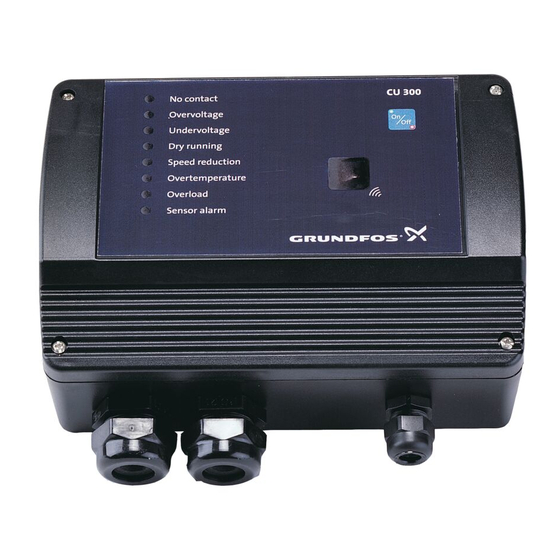
- Page 1 GRUNDFOS INSTRUCTIONS CU 300 Installation and operating instructions No contact Overvoltage Undervoltage Dry running Speed reduction Overtemperature Overload Sensor alarm CU 300 Installation and operating instructions http://net.grundfos.com/qr/i/96427972...
-
Page 4: Table Of Contents
CU 300 connected to RS-485 ..36 Mounting CU 300 ....7 12.1 Description ....36 CU 300 as an alarm unit. -
Page 5: General Information
Cleaning and user maintenance shall not be made by children without supervision. 1.1 Hazard statements The symbols and hazard statements below may appear in Grundfos installation and operating instructions, safety instructions and service instructions. DANGER Indicates a hazardous situation which, if not avoided, will result in death or serious personal injury. -
Page 6: General
The control unit CU 300 is developed for the SQE do the following: submersible pumps. • Start or stop the pump. CU 300 covers the voltage range 1 x 100-240 V - 10 %/+ 6 %, 50/60 Hz, PE. • Reset alarms. CU 300 has the following functions: •... -
Page 7: Mechanical Installation
Dimensions 4.2 Electrical installation 14. CU 300 with Grundfos GO CU 300 is supplied with a set of gaskets for the Pg screwed connections. The gaskets are to be used for the connection of cables or wires to ensure tight connections, IP55, and... -
Page 8: Electrical Installation
CU 300 must be connected in accordance with the rules and standards in force for the application in question. The supply voltage and frequency are marked on the nameplate. Make sure that CU 300 is suitable for the power supply on which it will be used. -
Page 9: Description Of Dry-Running Protection
If the pump power input falls below the dry-running speed power limit set in the Grundfos GO display "Dry- 10,700 min running stop", the pump will stop and CU 300 will indicate the dry-running alarm. Motor speed Related information Pump power input [Watt] 15.2.20 Dry-running protection... -
Page 10: Settings
"Dewatering" function in the display Dewatering. During dewatering, the green indicator light in the On/Off button on CU 300 is flashing to indicate that Setting of dry-running power limit (dry-running the pump has stopped. stop): 1. - Page 11 4.5.4 On/off times The dewatering function means that there is a dependence between the period of time during which the pump is running, the on time, and the period of time during which the pump is stopped, the off time. Figure On and off times shows an example of on and...
-
Page 12: Cu 300 With Constant-Pressure Control - 0 To 6 Bar
The pressure is registered by means of the pressure sensor, which transmits a signal to CU 300. CU 300 If you use a diaphragm tank of 8 litres, the pump will adjusts the pump performance accordingly by start at a flow rate of approx. - Page 13 Flow detection During pump operation, i.e. when water is consumed, CU 300 will adjust the pump speed to maintain a constant pressure. In order to stop the pump when no water is consumed, CU 300 performs flow detection every 10 seconds.
-
Page 14: Positioning The Pressure Sensor
5.3 Positioning the pressure sensor Pressure loss often causes inconvenience to the user. CU 300 keeps the pressure constant in the place where the pressure sensor is positioned. Pressure sensor position Pos. Description Tap 1 Tap 2 CU 300 fig.Pressure sensor position, tap 1 is placed close to the pressure sensor. -
Page 15: Electrical Installation
CU 300 must be connected in accordance with the rules and standards in force for the application in question. The supply voltage and frequency are marked on the nameplate. Make sure that CU 300 is suitable for the power supply on which it will be used. -
Page 16: Startup
5.5.1 Mains supply 5.5.4 Required Grundfos GO settings POWER, terminals 1, 2 and PE You must make the following Grundfos GO settings: Connect terminals 1 and 2 to the phase and neutral 1. In display "Control mode" select "Closed loop". -
Page 17: Cu 300 With Constant-Pressure Control - 0 To 10 Bar
(- 0.5 bar) The pressure is registered by means of the pressure Controlling (± 0.2 bar) sensor and transmitted to CU 300. CU 300 adjusts the pump performance accordingly. To ensure that the Dynamic (± 0.5 bar) pump is started when water is consumed, include a Flow flow switch in the system. -
Page 18: Positioning The Pressure Sensor
6.3 Positioning the pressure sensor Pressure loss often causes inconvenience to the user. CU 300 keeps the pressure constant in the place where the pressure sensor is positioned. Pressure sensor position Pos. Description Tap 1 Tap 2 CU 300 In fig. -
Page 19: Electrical Installation
CU 300 must be connected in accordance with the rules and standards in force for the application in question. The supply voltage and frequency are marked on the nameplate. Make sure that CU 300 is suitable for the power supply on which it will be used. -
Page 20: Startup
6.5.1 Mains supply 6.5.4 Required Grundfos GO settings POWER, terminals 1, 2 and PE You must make the following Grundfos GO settings: Connect terminals 1 and 2 to the phase and neutral 1. In display Control mode" select "Closed loop". -
Page 21: Cu 300 With Constant-Pressure Control - Two-Pump Operation
If the consumption exceeds the quantity the pump connected to CU 300 (master) is able to deliver, the pressure in the diaphragm tank will fall. The pump connected to CU 300 (slave) will be started in the two following situations: •... -
Page 22: Positioning The Pressure Sensor
If the flow is larger than the quantity the pumps are able to deliver at the desired pressure, the pressure follows the pump curve. See fig. Possible pressure variations during constant-pressure operation. Possible pressure variations during constant- pressure operation Pos. Description Stop (+ 0.5 bar) Pressure... -
Page 23: Electrical Installation
CU 300 must be connected in accordance with the rules and standards in force for the application in question. The supply voltage and frequency are marked on the nameplate. Make sure that CU 300 is suitable for the power supply on which it will be used. -
Page 24: Startup
7.5.1 Auxiliary relay Manual restarting is carried out by means of the On/Off button on CU 300. Connect CU 300 (master) to CU 300 (slave) as follows: 7.5.5 Flow switch and pressure sensor Connect the flow switch and the pressure sensor to Connections the control unit (A = master) as illustrated in fig. -
Page 25: Cu 300 With Sensors
8. CU 300 with sensors 100% 8.1 General CU 300 can be used in systems with one to three sensors connected. Figure Incorporating sensors shows an example of an installation incorporating sensors. pH 100% Limit settings Pos. Description Min. Alarm Max. -
Page 26: Sensor Functioning
2. The alarm signal relay operates. minimum water level. 3. The "Sensor alarm" indicator light on CU 300 is 4. The alarm appears in the Grundfos GO display "Alarms and warnings". -
Page 27: Electrical Installation
CU 300 must be connected in accordance with the rules and standards in force for the application in question. The supply voltage and frequency are marked on the nameplate. Make sure that CU 300 is suitable for the power supply on which it will be used. - Page 28 You set the limits for the signal from an external Maximum cross-section of the leads to be connected sensor in the Grundfos GO in the "Analog input 1" is 6 mm and "Analog input 2" displays.
-
Page 29: Cu 300 Connected To Potentiometer
9. CU 300 connected to potentiometer 9.1 Description Using an external potentiometer enables: • Manual control of the motor speed, and thereby of pump performance. Manual starting/stopping of the pump. To stop the pump, turn the potentiometer (SPP 1) to "STOP". -
Page 30: Electrical Installation
CU 300 must be connected in accordance with the rules and standards in force for the application in question. The supply voltage and frequency are marked on the nameplate. Make sure that CU 300 is suitable for the power supply on which it will be used. -
Page 31: Cu 300 Connected To Water Meter
Description On/Off button on CU 300. CU 300 9.2.4 Potentiometer SPP 1 Water meter (pulse flow meter) Connections between the SPP 1 and CU 300: SPP 1 CU 300 17 (SENSOR 2 +24 VDC) 19 (SENSOR 2 GND) 12 (DIG IN) -
Page 32: Electrical Installation
CU 300 must be connected in accordance with the rules and standards in force for the application in question. The supply voltage and frequency are marked on the nameplate. Make sure that CU 300 is suitable for the power supply on which it will be used. -
Page 33: Constant Water Level
2. Set "Flow per pulse": 11.2 Function Example: "10 l/pulse". CU 300 controls the pump speed and consequently adjusts the pump performance to the borehole yield. When you have set a value in this display, the actual 1. When the water level is much higher than the flow will appear in status display "Digital input". -
Page 34: Electrical Installation
CU 300 must be connected in accordance with the rules and standards in force for the application in question. The supply voltage and frequency are marked on the nameplate. Make sure that CU 300 is suitable for the power supply on which it will be used. - Page 35 11.3.1 Mains supply 11.3.6 Required Grundfos GO settings POWER, terminals 1, 2 and PE You must make the following Grundfos GO settings: Connect terminals 1 and 2 to the phase and neutral 1. In display "Control mode" select "Closed loop".
-
Page 36: Cu 300 Connected To Rs-485
PC directly via the PC Tool link and GENIbus. The installation shown in the example enables configuration, fault finding and servicing of the CIU 27X installation by means of a PC with a PC Tool CU 300 software. RS-485 GENIbus Pos. -
Page 37: Electrical Installation
CU 300 must be connected in accordance with the rules and standards in force for the application in question. The supply voltage and frequency are marked on the nameplate. Make sure that CU 300 is suitable for the power supply on which it will be used. - Page 38 Connect the PE terminal to the green/yellow earth lead. You must connect each PE terminal to an earth CU 300 can communicate with a PC with the PC Tool lead of its own. CU 300 installed. Maximum cross-section of the leads to be connected You need a PC Tool link adapter to communicate with a PC.
-
Page 39: Alarm Functions
The alarm indication "No contact" will also appear if 16. Technical data the pump and CU 300 do not have the same number (allocated by the Grundfos GO). The problem may occur e.g. in connection with replacing a motor or a CU 300. -
Page 40: Undervoltage
Borehole service is Borehole filter is blocked. Related information required. 16. Technical data Restarting After 5 minutes (factory setting), or the period set by means of the Grundfos GO display "Automatic restarting", the motor will restart automatically. -
Page 41: Speed Reduction
13.5 Speed reduction 13.6 Overtemperature At a moderate undervoltage or overload of the motor, The motor temperature is monitored continuously the speed is reduced, but the motor is not stopped. during operation. The speed reduction indicator light is on, and at the The motor is factory-set to a maximum value. -
Page 42: Overload
Restarting Pump is defective. Pump must be serviced. After 5 minutes (factory setting), or the period set by means of the Grundfos GO display "Automatic Sand or gravel in pump. Pump must be serviced. restarting", the motor will restart automatically. -
Page 43: Cu 300 With Grundfos Go
(A) in the On/Off button will flash. For general use of the Grundfos GO, see the operating instructions for this unit. The menu structure for the Grundfos GO and CU 300 is divided into three main menus, each containing a number of displays. -
Page 44: Menu Overview
14.1 Menu overview Status Section External setpoint 15.1.1 External setpoint Controlled from 15.1.2 Controlled from Value, sensor 1 15.1.3 Value, sensor 1 and 2 Value, sensor 2 Motor temperature 15.1.4 Motor temperature Motor speed 15.1.5 Motor speed Digital input 15.1.6 Digital input Specific energy 15.1.7 Specific energy Accumulated flow... - Page 45 Settings Section Start delay 15.2.17 Start delay Dewatering 15.2.18 Dewatering Dewatering max. on time 15.2.19 Dewatering, maximum "On" and "Off" time Dewatering max. off time Dry-running protection 15.2.20 Dry-running protection Dry-running stop 15.2.21 Dry-running stop Maximum speed 15.2.22 Maximum speed Buttons on product 15.2.23 Buttons on product Number...
-
Page 46: Description Of Functions
15.1.10 Energy consumption You can read the total energy consumption in this 15.1 Status display. The "Status" menu for CU 300 offers the possibility of reading operating parameters. 15.1.1 External setpoint You can read the value of the external setpoint in this display. -
Page 47: Settings
The value of number of starts is accumulated from Example: Constant-pressure control. See section the pump's birth and it cannot be reset. CU 300 with constant-pressure control - 0 to 10 The value is stored in the motor electronics, and it is bar. - Page 48 1 and 2. The actual setpoint is calculated by CU 300 and shown in display Setpoint. If an SPP 1 potentiometer is connected, the internal voltage supply of CU 300 is used to generate the signal. See section CU 300 connected to potentiometer.
- Page 49 15.2.9 Warning, temperature Related information Set the temperature warning limit of the motor. 15.2.11 Flow per pulse Setting range: "-" (not active), 2, 4, 6, ..85 °C. 15.2.11 Flow per pulse In this display the pumped volume per pulse is set. The maximum temperature depends on Setting range: 0.0, 0.1, 0.2, 0.3, ..20, 21, 22, ..100 the motor type.
- Page 50 The time is doubled up to Operating indication a stop time of 4 hours. After 10 hours of operation The dry-running alarm indication on CU 300 is without an alarm, the restart time is automatically set automatically disabled, when this display setting is made.
- Page 51 In connection with bus communication, you must Power consumption. allocate a number to CU 300 and the pump. Factory setting If CU 300 and the pump do not have the same number, the alarm "No contact" will be indicated. Motor size Dry-running stop Factory setting 0.7 kW...
-
Page 52: Alarms And Warnings
Description No fault indication No alarms are registered by CU 300. No contact to pump No communication between CU 300 and the pump. Overvoltage The supply voltage exceeds the limit value. Undervoltage The supply voltage is below the limit value. -
Page 53: Technical Data
Screened cable is recommended. Materials Maximum cable length: 100 m. The CU 300 box is made of black PPO. Voltage signal: 0-10 VDC/2-10 VDC, R = 11 kΩ. EMC (Electromagnetic compatibility) Tolerance: ± 3 % at maximum voltage signal. - Page 54 8.4 A 11 A 12.3 A 12.1 A Sensor alarm "No sensor used" (Grundfos GO setting). See section 15.2.4 Analog inputs) 200-240 V motors: Operation is guaranteed up to 280 VAC. 100-115 V motors: Operation is guaranteed up to 150 VAC.
-
Page 55: Disposing Of The Product
This product or parts of it must be disposed of in an environmentally sound way. 1. Use the public or private waste collection service. 2. If this is not possible, contact the nearest Grundfos company or service workshop. See also end-of-life information at www.grundfos.com/product-recycling. 18. Document quality feedback To provide feedback about this document, scan the QR-code using your phone’s camera or a QR code... - Page 56 DE: EU-Konformitätserklärung We, Grundfos, declare under our sole responsibility Wir, Grundfos, erklären in alleiniger Verantwortung, that the product CU 300, to which the declaration dass das Produkt CU 300, auf das sich diese below relates, is in conformity with the Council Erklärung bezieht, mit den folgenden Richtlinien des...
- Page 57 Hazardous Substances in Electrical and Electronic Equipment Regulations 2012 Standards used: EN IEC 63000:2018 This UK declaration of conformity is only valid when published as part of the Grundfos operating and installation instructions (publication number 96427972). Bjerringbro, 1st November 2022 Frank S. Madsen...
- Page 58 Moroccan declaration of conformity GB: Moroccan declaration of conformity FR: Déclaration de conformité marocaine We, Grundfos, declare under our sole responsibility Nous, Grundfos, déclarons sous notre seule that the products to which the declaration below responsabilité que les produits auxquels se réfère relates, are in conformity with Moroccan laws, cette déclaration, sont conformes aux lois,...
- Page 59 Bjerringbro, 1st November 2022 Frank S. Madsen Capability Manager, Electronics Grundfos Holding A/S Poul Due Jensens Vej 7 8850 Bjerringbro, Denmark GB: Manufacturer and person empowered to sign the Moroccan declaration of conformity. FR: Fabricant et personne habilitée à signer la Déclaration de conformité...
- Page 60 Argentina China Greece Bombas GRUNDFOS de Argentina S.A. GRUNDFOS Pumps (Shanghai) Co. Ltd. GRUNDFOS Hellas A.E.B.E. Ruta Panamericana km. 37.500industin 10F The Hub, No. 33 Suhong Road 20th km. Athinon-Markopoulou Av. 1619 - Garín Pcia. de B.A. Minhang District P.O. Box 71 Tel.: +54-3327 414 444...
- Page 61 Fax: +66-2-725 8998 Fax: + 370 52 395 431 Москва, RU-109544, Russia Turkey Тел. (+7) 495 564-88-00 (495) 737-30-00 Malaysia GRUNDFOS POMPA San. ve Tic. Ltd. Факс (+7) 495 564 8811 GRUNDFOS Pumps Sdn. Bhd. Sti. E-mail grundfos.moscow@grundfos.com 7 Jalan Peguam U1/25 Gebze Organize Sanayi Bölgesi...
- Page 62 96427972 12.2022 ECM: 1352243 www.grundfos.com...
Need help?
Do you have a question about the CU 300 and is the answer not in the manual?
Questions and answers