Table of Contents
Advertisement
Quick Links
(/xwiki/bin/view/Main/) / Home (/xwiki/bin/view/Main/)
/ User Manual for LoRaWAN End Nodes (/xwiki/bin/view
/Main/User%20Manual%20for%20LoRaWAN%20End%20Nodes/)
/ LLDS40-LoRaWAN LiDAR ToF Distance Sensor User Manual (/xwiki/bin/view
/Main/User%20Manual%20for%20LoRaWAN%20End%20Nodes/LLDS40-
LoRaWAN%20LiDAR%20ToF%20Distance%20Sensor%20User%20Manual/)
LLDS40-LoRaWAN LiDAR ToF Distance
Sensor User Manual
Last modified by Xiaoling (/xwiki/bin/view/XWiki/Xiaoling) on 2022/11/03 08:53
Advertisement
Table of Contents

Subscribe to Our Youtube Channel
Related Manuals for Dragino LLDS40


Summary of Contents for Dragino LLDS40
- Page 1 (/xwiki/bin/view/Main/) / Home (/xwiki/bin/view/Main/) / User Manual for LoRaWAN End Nodes (/xwiki/bin/view /Main/User%20Manual%20for%20LoRaWAN%20End%20Nodes/) / LLDS40-LoRaWAN LiDAR ToF Distance Sensor User Manual (/xwiki/bin/view /Main/User%20Manual%20for%20LoRaWAN%20End%20Nodes/LLDS40- LoRaWAN%20LiDAR%20ToF%20Distance%20Sensor%20User%20Manual/) LLDS40-LoRaWAN LiDAR ToF Distance Sensor User Manual Last modified by Xiaoling (/xwiki/bin/view/XWiki/Xiaoling) on 2022/11/03 08:53...
-
Page 2: Table Of Contents
◦ 3.2 Distance Measurement Characteristics ◦ 3.3 Notice of usage: ◦ 3.4 Reflectivity of different objects: • 4. Configure LLDS40 via AT Command or LoRaWAN Downlink ◦ 4.1 Set Transmit Interval Time ◦ 4.2 Set Interrupt Mode ◦ 4.3 Get Firmware Version Info •... -
Page 3: Introduction
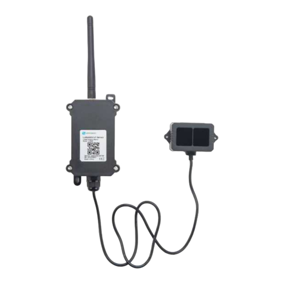
LLDS40 is powered by 8500mAh Li-SOCI2 battery, it is designed for long term use up to 5 years. Each LLDS40 is pre-load with a set of unique keys for LoRaWAN registrations, register these keys to local... -
Page 4: Features
1.2 Features • LoRaWAN 1.0.3 Class A • Ultra-low power consumption • Laser technology for distance detection • Measure Distance: 0.1m ~ 40m @ 90% Reflectivity • Monitor Battery Level • Bands: CN470/EU433/KR920/US915/EU868/AS923/AU915/IN865 • AT Commands to change parameters • Uplink on periodically •... -
Page 5: Probe Dimension
• Material of enclosure : ABS+PC • Wire length : 75cm 1.4 Probe Dimension 1.5 Applications • Horizontal distance measurement • Oil Tank • Object proximity and presence detection • Intelligent trash can management system • Robot obstacle avoidance • Automatic control •... -
Page 6: Configure Llds40 To Connect To Lorawan Network
2.1 How it works The LLDS40 is configured as LoRaWAN OTAA Class A mode by default. It has OTAA keys to join LoRaWAN network. To connect a local LoRaWAN network, you need to input the OTAA keys in the LoRaWAN IoT server and power on the LLDS40. - Page 7 Step 1: Create a device in TTN with the OTAA keys from LLDS40. Each LLDS40 is shipped with a sticker with the default device EUI as below: You can enter this key in the LoRaWAN Server portal. Below is TTN screenshot:...
- Page 8 Add APP EUI and DEV EUI...
- Page 9 Add APP EUI in the application...
- Page 10 Add APP KEY...
- Page 11 Put a Jumper on JP2 to power on the device. ( The Switch must be in FLASH position). Step 3: The LLDS40 will auto join to the TTN network. After join success, it will start to upload messages to TTN and you can see the messages in the panel.
-
Page 12: Uplink Payload
2.3 Uplink Payload LLDS40 will uplink payload via LoRaWAN with below payload format: Uplink payload includes in total 11 bytes. Size(bytes) Value Temperature Distance Distance Interrupt LiDAR Message DS18B20 signal flag temp Type strength 2.3.1 Battery Info Check the battery voltage for LLDS40. -
Page 13: Ds18B20 Temperature Sensor
If payload is: FF3FH : (FF3F & FC00 == 1) , temp = (FF3FH - 65536)/10 = -19.3 degrees. 2.3.3 Distance Indicates the distance value measured by the LLDS40. The default unit is cm and the range is 0-4000. Example: If the data you get from the register is 0x0B 0xEA, the distance between the sensor and the measured object is 0BEA(H) = 3050 (D)/10 = 305cm. -
Page 14: Interrupt Pin
2) When the sensor detects invalid data: 3) When the sensor is not connected: 2.3.5 Interrupt Pin This data field shows if this packet is generated by interrupt or not. Click here for the hardware and software set up. Note: The Internet Pin is a separate pin in the screw terminal. See pin mapping. Example: 0x00: Normal uplink packet. -
Page 15: Message Type
Reply configures info Configure Info Payload 2.3.8 Decode payload in The Things Network While using TTN network, you can add the payload format to decode the payload. The payload decoder function for TTN is here: LLDS40 TTN Payload Decoder: https://github.com/dragino/dragino-end-node-decoder/tree/main /LLDS40 (https://github.com/dragino/dragino-end-node-decoder/tree/main/LLDS40) -
Page 16: Uplink Interval
2.4 Uplink Interval The LLDS40 by default uplink the sensor data every 20 minutes. User can change this interval by AT Command or LoRaWAN Downlink Command. See this link: Change Uplink Interval (/xwiki/bin/view /Main/End%20Device%20AT%20Commands%20and%20Downlink%20Command /#H4.1ChangeUplinkInterval) 2.5 Show Data in DataCake IoT Server DATACAKE (https://datacake.co/) - Page 17 Step 3: Create an account or log in Datacake. Step 4: Create LLDS40 product.
- Page 20 Step 5: add payload decode ...
-
Page 21: Frequency Plans
After added, the sensor data arrive TTN, it will also arrive and show in Datacake. 2.6 Frequency Plans The LLDS40 uses OTAA mode and below frequency plans by default. If user want to use it with different frequency plan, please refer the AT command sets. -
Page 22: Eu863-870 (Eu868)
2.6.1 EU863-870 (EU868) Uplink: 868.1 - SF7BW125 to SF12BW125 868.3 - SF7BW125 to SF12BW125 and SF7BW250 868.5 - SF7BW125 to SF12BW125 867.1 - SF7BW125 to SF12BW125 867.3 - SF7BW125 to SF12BW125 867.5 - SF7BW125 to SF12BW125 867.7 - SF7BW125 to SF12BW125 867.9 - SF7BW125 to SF12BW125 868.8 - FSK ... -
Page 23: Au915-928(Au915)
Uplink: 486.3 - SF7BW125 to SF12BW125 486.5 - SF7BW125 to SF12BW125 486.7 - SF7BW125 to SF12BW125 486.9 - SF7BW125 to SF12BW125 487.1 - SF7BW125 to SF12BW125 487.3 - SF7BW125 to SF12BW125 487.5 - SF7BW125 to SF12BW125 487.7 - SF7BW125 to SF12BW125 Downlink: 506.7 - SF7BW125 to SF12BW125 506.9 - SF7BW125 to SF12BW125... -
Page 24: As920-923 & As923-925 (As923)
2.6.5 AS920-923 & AS923-925 (AS923) Default Uplink channel: 923.2 - SF7BW125 to SF10BW125 923.4 - SF7BW125 to SF10BW125 Additional Uplink Channel: (OTAA mode, channel added by JoinAccept message) AS920~AS923 for Japan, Malaysia, Singapore: 922.2 - SF7BW125 to SF10BW125 922.4 - SF7BW125 to SF10BW125 922.6 - SF7BW125 to SF10BW125 922.8 - SF7BW125 to SF10BW125... -
Page 25: In865-867 (In865)
Default channel: 922.1 - SF7BW125 to SF12BW125 922.3 - SF7BW125 to SF12BW125 922.5 - SF7BW125 to SF12BW125 Uplink: (OTAA mode, channel added by JoinAccept message) 922.1 - SF7BW125 to SF12BW125 922.3 - SF7BW125 to SF12BW125 922.5 - SF7BW125 to SF12BW125 922.7 - SF7BW125 to SF12BW125 922.9 - SF7BW125 to SF12BW125 923.1 - SF7BW125 to SF12BW125... -
Page 26: Firmware Change Log
The LLDS40 has an internal LED which is to show the status of different state. • The sensor is detected when the device is turned on, and it will flash 4 times quickly when it is detected. • Blink once when device transmits a packet. -
Page 27: Notice Of Usage
The detection angle of the LLDS40 is 3 degrees, and the size of the light spot at different distances is the side length of the detection range. The size of the light spot at different distances is the side length of the detection range. -
Page 28: Configure Llds40 Via At Command Or Lorawan Downlink
• General system settings like: uplink interval. • LoRaWAN protocol & radio related command. They are same for all Dragino Device which support DLWS-005 LoRaWAN Stack. These commands can be found on the wiki: End Device AT Commands and Downlink Command (/xwiki/bin/view /Main/End%20Device%20AT%20Commands%20and%20Downlink%20Command/) ... -
Page 29: Set Transmit Interval Time
• Commands special design for LLDS40 These commands only valid for LLDS40, as below: 4.1 Set Transmit Interval Time Feature: Change LoRaWAN End Node Transmit Interval. AT Command: AT+TDC Downlink Command: 0x01 Format: Command Code (0x01) followed by 3 bytes time value. -
Page 30: Get Firmware Version Info
Downlink Command: 0x06 Format: Command Code (0x06) followed by 3 bytes. This means that the interrupt mode of the end node is set to 0x000003=3 (rising edge trigger), and the type code is 06. • Example 1: Downlink Payload: 06000000 // Turn off interrupt mode •... -
Page 31: Battery & How To Replace
Firmware Sensor Reserve Message Type Band band Version Type Type Always 0x02 Software Type: Always 0x03 for LLDS40 Frequency Band: *0x01: EU868 *0x02: US915 *0x03: IN865 *0x04: AU915 *0x05: KZ865 *0x06: RU864 *0x07: AS923 *0x08: AS923-1 *0x09: AS923-2 *0xa0: AS923-3 Sub-Band: value 0x00 ~ 0x08 Firmware Version: 0x0100, Means: v1.0.0 version... -
Page 32: Battery Type
5.1 Battery Type LLDS40 is equipped with a 8500mAH ER26500 Li-SOCI2 battery (https://www.dragino.com/downloads /index.php?dir=datasheet/Battery/ER26500/) . The battery is un-rechargeable battery with low discharge rate targeting for 8~10 years use. This type of battery is commonly used in IoT target for long-term running, such as water meter. - Page 33 5.3 Power Consumption Analyze Dragino Battery powered product are all runs in Low Power mode. We have an update battery calculator which base on the measurement of the real device. User can use this calculator to check the battery life and calculate the battery life if want to use different transmit interval.
- Page 34 5.3.2 Replace the battery You can change the battery in the LLDS40.The type of battery is not limited as long as the output is between 3v to 3.6v. On the main board, there is a diode (D1) between the battery and the main circuit. If you need to use a battery with less than 3.3v, please remove the D1 and shortcut the two pads of it so...
- Page 35 USB TTL TXD <----> UART_RXD USB TTL RXD <----> UART_TXD In the PC, you need to set the serial baud rate to 9600 to access the serial console for LLDS40. LLDS40 will output system info once power on as below:...
- Page 36 Valid AT Command please check Configure Device. 7. FAQ 7.1 How to change the LoRa Frequency Bands/Region You can follow the instructions for how to upgrade image. When downloading the images, choose the required image file for download. 8. Trouble Shooting 8.1 ...
- Page 37 • IN865: LoRaWAN IN865 band • CN470: LoRaWAN CN470 band 10. Packing Info Package Includes: • LLDS40 LoRaWAN LiDAR Distance Sensor x 1 Dimension and weight: • Device Size: cm • Device Weight: g • Package Size / pcs : cm...
- Page 38 However, your questions will be answered as soon as possible in the before-mentioned schedule. • Provide as much information as possible regarding your enquiry (product models, accurately describe your problem and steps to replicate it etc) and send a mail to support@dragino.com (http://../../../../../../D:%5C%E5%B8%82%E5%9C%BA%E8%B5%84%E6%96%99%5C%E8%AF %B4%E6%98%8E%E4%B9%A6%5CLoRa%5CLT%E7%B3%BB%E5%88%97 %5Csupport@dragino.com) .
Need help?
Do you have a question about the LLDS40 and is the answer not in the manual?
Questions and answers