Table of Contents
Advertisement
Quick Links
LHT65 Temperature & Humidity Sensor User Manual
Document Version: 1.1
Image Version: v1.3
Version
Description
0.9
Draft
1.0
Release
1.1
Modify activation process, Add TTN Payload Decode
1.2
Fix ACT typo, Add cayenne photo. Battery Analyze. Add notice for single
channel use.
LHT65 Temperature & Humidity sensor
www.dragino.com
Date
2019-May-14
2019-Jun-15
2019-Aug-28
1 / 40
Advertisement
Table of Contents

Related Manuals for Dragino LHT65


Summary of Contents for Dragino LHT65
- Page 1 LHT65 Temperature & Humidity Sensor User Manual Document Version: 1.1 Image Version: v1.3 Version Description Date Draft 2019-May-14 Release 2019-Jun-15 Modify activation process, Add TTN Payload Decode 2019-Aug-28 Fix ACT typo, Add cayenne photo. Battery Analyze. Add notice for single channel use.
-
Page 2: Table Of Contents
Introduction ..........................4 What is LHT65 Temperature & Humidity Sensor ................ 4 Features ............................5 Specifications ..........................5 Power Consumption ........................5 Applications ..........................6 Operation Mode ........................7 How to activate LHT65? ......................7 How it works? ..........................7 Example to join LoRaWAN network .................... - Page 3 How to change the LoRa Frequency Bands/Region? ..............34 How to choose the right frequency band set for US915, AU915, CN470 bands? ..... 34 How to set up LHT65 to work with Single Channel Gateway such as LG01/LG02? ....36 Trouble Shooting ........................38 Order Info ..........................
-
Page 4: Introduction
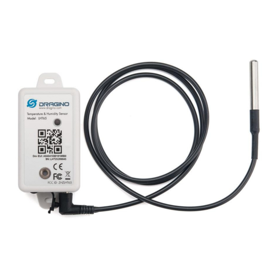
1. Introduction 1.1 What is LHT65 Temperature & Humidity Sensor The Dragino LHT65 Temperature & Humidity sensor is a Long Range LoRaWAN Sensor. It includes built-in SHT20 Temperature & Humidity sensor and has an external sensor connector to connect to external sensors such as Temperature Sensor, Soil Moisture Sensor, Tilting Sensor The LHT65 allows users to send data and reach extremely long ranges. -
Page 5: Features
-55°C to +125°C Operating Range: -55 ~ 125 °C °C 1.4 Power Consumption LHT65 (without external sensor): Idle: 3uA. Transmit: max 130mA. LHT65 + E1 Sensor: Idle: 4uA, Transmit: max 130mA. LHT65 Temperature & Humidity sensor 5 / 40... -
Page 6: Applications
1.5 Storage & Operation Temperature -40°C to +85°C 1.6 Applications Smart Buildings & Home Automation Logistics and Supply Chain Management Smart Metering Smart Agriculture Smart Cities Smart Factory LHT65 Temperature & Humidity sensor 6 / 40... -
Page 7: Operation Mode
(IDLE mode), in STOP mode, device has the same power consumption as Deep Sleep mode. The LHT65 is set in deep sleep mode by default; The ACT button on the bottom of device is used to switch to different modes:... - Page 8 Step 1: Create a device in TTN with the OTAA keys from LHT65. Each LHT65 is shipped with a sticker with the default device EUI as below: User can enter these keys in the LoRaWAN Server portal. Below is TTN screen shot: Add APP EUI in the application.
-
Page 9: Uplink Payload
Step 2: Use ACT button to activate LHT65 and it will auto join to the TTN network. After join success, it will start to upload sensor data to TTN and user can see in the panel. 2.4 Uplink Payload The uplink payload includes totally 11 bytes. -
Page 10: Decoder In Ttn
| bytes[3]; if(bytes[2] & 0x80) {value |= 0xFFFF0000;} var temp_SHT=(value/100).toFixed(2);//SHT20,temperature,units:℃ value=bytes[4]<<8 | bytes[5]; var hum_SHT=(value/10).toFixed(1);//SHT20,Humidity,units:% value=bytes[7]<<8 | bytes[8]; if(bytes[7] & 0x80) {value |= 0xFFFF0000;} var temp_ds=(value/100).toFixed(2);//DS18B20,temperature,units:℃ return { BatV:batV, TempC_DS:temp_ds, TempC_SHT:temp_SHT, Hum_SHT:hum_SHT LHT65 Temperature & Humidity sensor 10 / 40... -
Page 11: Bat-Battery Info
00(b): Ultra Low ( BAT <= 2.50v) 01(b): Low (2.50v <=BAT <= 2.55v) 10(b): OK (2.55v <= BAT <=2.65v) 11(b): Good (BAT >= 2.65v) Check the battery voltage for LHT65. Bat status=(0xCBF6>>14)&0xFF=11(B),very good battery voltage =0xCBF6&0x3FFF=0x0BF6=3062mV 2.4.3 Built-in Temperature 0x0B0D/100=28.29℃ Temperature: 0xF5C6-65536)/100=-26.18℃... -
Page 12: Built-In Humidity
DS18B20 temp= 0xF54F-65536)/100=-27.37℃ The last 2 bytes of data are meaningless If the external sensor is 0x01, and there is no DS18B20 connected. The temperature will be set to 7FFF which is 327.67℃ LHT65 Temperature & Humidity sensor 12 / 40... -
Page 13: Downlink Payload
Cayenne to connect to TTN and see the data in Cayenne. Below are the steps: Step 1: Be sure that your device is programmed and properly connected to the network at this time. LHT65 Temperature & Humidity sensor 14 / 40... - Page 14 Step 2: To configure your Application to forward data to Cayenne you will need to add an Integration. To add the Cayenne integration, perform the following steps: LHT65 Temperature & Humidity sensor 15 / 40...
- Page 15 LHT65 Temperature & Humidity sensor 16 / 40...
-
Page 16: Read Stored Sensor Data
By default, LHT65 stores one set of data every 5 minutes. LHT65 has reversed 400 sectors for storage; each sector can store 8 sets data so total 3200 sets of data can be stored. LHT65 use circle storage method, means the storage position reach the 400... -
Page 17: Frequency Plans
AT+CLRDTA: Clear the storage, record position back to 1 AT+RTP: Set record time period, default value 5 minute (AT+RTP=5). If RTP is set to 0, LHT65 will disable the record feature ( RTP can be set by downlink command) AT+DATE=19 05 30 16 21 58 set current time to 2019-5-30 16:21:58,AT+DATE=? to check the... -
Page 18: Cn470-510 (Cn470)
505.3 - SF12BW125 (RX2 downlink only) 2.8.4 AU915-928(AU915) Default use CHE=2 Uplink: 916.8 - SF7BW125 to SF12BW125 917.0 - SF7BW125 to SF12BW125 917.2 - SF7BW125 to SF12BW125 917.4 - SF7BW125 to SF12BW125 917.6 - SF7BW125 to SF12BW125 LHT65 Temperature & Humidity sensor 19 / 40... -
Page 19: As920-923 & As923-925 (As923)
923.6 - SF7BW125 to SF10BW125 923.8 - SF7BW125 to SF10BW125 924.0 - SF7BW125 to SF10BW125 924.2 - SF7BW125 to SF10BW125 924.4 - SF7BW125 to SF10BW125 924.6 - SF7BW125 to SF10BW125 Downlink: Uplink channels 1-8 (RX1) LHT65 Temperature & Humidity sensor 20 / 40... -
Page 20: Kr920-923 (Kr920)
Uplink channels 1-3 (RX1) 866.550 - SF10BW125 (RX2) LED Indicator The LHT65 has a triple color LED which for easy showing different stage . While user press ACT button, the LED will work as per LED status with ACT button. -
Page 21: Use At Command
3. Use AT Command 3.1 Access AT Command LHT65 supports AT Command set. User can use a USB to TTL adapter plus the Program Cable to connect to LHT65 for using AT command, as below. Connection: USB to TTL GND <--> Dupont black pin ... - Page 22 AT+<CMD>=? : Get the value ATZ: Trig a reset of the MCU AT+FDR: Reset Parameters to Factory Default, Keys Reserve AT+DEUI: Get or Set the Device EUI AT+DADDR: Get or Set the Device Address LHT65 Temperature & Humidity sensor 23 / 40...
- Page 23 AT+CHE: Get or Set eight channels mode,Only for US915,AU915,CN470 AT+DATE: Get or Set real time AT+PDTA: Print the sector data from start page to stop page AT+PLDTA: Print the last few sets of data LHT65 Temperature & Humidity sensor 24 / 40...
- Page 24 AT+CLRDTA: Clear the storage, record position back to 1st AT+SLEEP: Set sleep mode AT+EXT: Get or Set external sensor model AT+RTP: Get or Set record time period in min AT+CFG: Print all configurations LHT65 Temperature & Humidity sensor 25 / 40...
-
Page 25: Common At Command Sequence
If device has not joined network yet: 123456 AT+FDR 123456 AT+NJM=0 If device already joined network: AT+NJM=0 3.2.2 Single-channel ABP mode (Use with LG01/LG02) Please refer this link: How to Set Single Channel Mode. LHT65 Temperature & Humidity sensor 26 / 40... -
Page 26: Battery Analyze
The discharge curve is not linear so can’t simply use percentage to show the battery level. Below is the battery performance. Minimum Working Voltage for the LHT65: LHT65: 2.45v ~ 3.6v ... -
Page 27: Power Consumption Analyze
3.3.2 Power consumption Analyze Below is the transmit power consumption of the system: Deep Sleep (Stop mode): a) LHT65 without sensor. ~ 3uA b) With E1 sensor: ~ 4uA Sampling current while reading E1. Built-in sensor sampling time: 120ms. 2mA ... - Page 28 Combine two RX windows together. There is a power consumption tool for easy analyze. And below is the analyze result. Ignore the 11 year, because the battery has a max 2% discharge per year. LHT65 Temperature & Humidity sensor 29 / 40...
-
Page 29: Sensors & Accessories
-10°C to +85°C °C ±2 accuracy from -55°C to +125°C °C Operating Range: -40 ~ 125 °C to 125 °C °C Working voltage 2.35v ~ 5v LHT65 Temperature & Humidity sensor 30 / 40... -
Page 30: Faq
5. FAQ 5.1 How to upgrade the firmware? The LHT65 is shipped with a program cable, which is used to upload image to LHT65 for: Support new features For bug fix Change LoRaWAN bands. https://youtu.be/0xpSWTCuDGQ Video Instruction is here: The latest firmware and changelog can be found at below link: http://www.dragino.com/downloads/index.php?dir=LHT65/Firmware/... - Page 31 Step1: Install ST-LINK driver first and then install ST-LINK Utility Step2: Download the LHT65 Image files. http://www.dragino.com/downloads/index.php?dir=LHT65/Firmware/ Step3: click the blue global “settings” button on ST-LINK. Click ok LHT65 Temperature & Humidity sensor 32 / 40...
- Page 32 Step4: The led on the ST-LINK adapter will now blinking, click program verify button to select the image to be upgraded. LHT65 Temperature & Humidity sensor 33 / 40...
-
Page 33: How To Change The Lora Frequency Bands/Region
LoRaWAN 1.0.3 Regional Parameters.xlsx The LHT65 choose CHE=2 by default(US915/AU915). If user has issue to join the LoRaWAN network, please check if the frequency band matches the LoRaWAN network settings. If not, properly need to use AT+CHE command to change. - Page 34 927.2 927.4 927.6 927.8 Channel 56-63 CN470 Uplink Channels(125KHz,4/5,Unit:MHz,CHS=0) ENABLE Channel 80-95 486.3 486.5 486.7 486.9 487.1 487.3 487.5 487.7 Channel 80-87 487.9 488.1 488.3 488.5 488.7 488.9 489.1 489.3 Channel 88-95 LHT65 Temperature & Humidity sensor 35 / 40...
-
Page 35: How To Set Up Lht65 To Work With Single Channel Gateway Such As Lg01/Lg02
5.4 How to set up LHT65 to work with Single Channel Gateway such as LG01/LG02? In this case, users need to set LHT65 to work in ABP mode & transmit in only one frequency. Assume we have a LG02 working in the frequency 868400000 now, below is the step. -
Page 36: Order Info
External sensor can be ordered separately by using the sensor model + ES as prefix: Part Number: ES-YY Example: ES-E1 8. Packing Info Package Includes: LHT65 Temperature & Humidity Sensor x 1 Program cable x 1 Optional external sensor Dimension and weight: Device Size: cm Device Weight: ... -
Page 37: Support
This equipment complies with FCC radiation exposure limits set forth for an uncontrolled environment. This equipment should be installed and operated with Minimum distances 20cm between the radiator include antenna & your body. LHT65 Temperature & Humidity sensor 40 / 40...
Need help?
Do you have a question about the LHT65 and is the answer not in the manual?
Questions and answers