Table of Contents
Advertisement
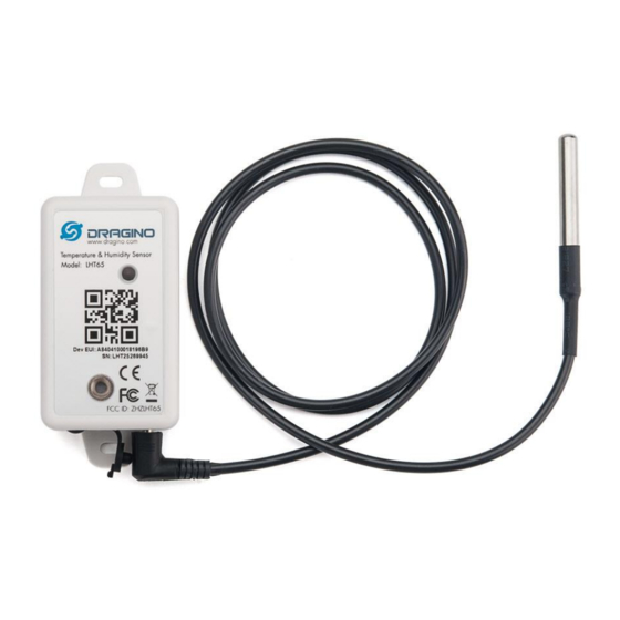
LHT65 Temperature & Humidity Sensor User Manual
Document Version: 1.8.0
Image Version: v1.8
Version
Description
0.9
Draft
1.0
Release
1.1
Modify activation process, Add TTN Payload Decode
1.2
Fix ACT typo, Add cayenne photo. Battery Analyze. Add notice for single
channel use. Add trouble shooting.
1.3
Add External Temperature Sensor pin connection, Improve ST-Link v2
connection description.
1.3.1
Correct myDevices description
1.3.2
Add how to reset device
LHT65 Temperature & Humidity sensor
www.dragino.com
Date
2019-May-14
2019-Jun-15
2019-Aug-28
2019-Nov-27
2019-Dec-29
2019-Dec-31
2020-Jan-17
1 / 56
Advertisement
Table of Contents

Related Manuals for Dragino LHT65


Summary of Contents for Dragino LHT65
- Page 1 LHT65 Temperature & Humidity Sensor User Manual Document Version: 1.8.0 Image Version: v1.8 Version Description Date Draft 2019-May-14 Release 2019-Jun-15 Modify activation process, Add TTN Payload Decode 2019-Aug-28 Fix ACT typo, Add cayenne photo. Battery Analyze. Add notice for single 2019-Nov-27 channel use.
- Page 2 Fix typo for A2 downlink command to change Interrupt 2020-Jun-30 1.7.3 Fix typo for uplink interval , it should be 20 minutes in default settings 2020-Jul-15 1.8.0 Upgrade to v1.8 firmware, 2021-Jan-29 Add Datalog feature, update to LoRaWAN stack DR-LWS-005 LHT65 Temperature & Humidity sensor 2 / 56...
-
Page 3: Table Of Contents
Set Device Time ......................27 2.6.3 Poll sensor value ......................28 2.6.4 Datalog Uplink payload ....................29 Alarm Mode..........................30 LED Indicator ..........................32 Configure LHT65 via AT Command or LoRaWAN Downlink ............33 LHT65 Temperature & Humidity sensor 3 / 56... - Page 4 How to upgrade the firmware? ....................47 How to change the LoRa Frequency Bands/Region? ..............51 How to set up LHT65 to work with Single Channel Gateway such as LG01/LG02? ....51 How to reset LHT65? ........................ 53 What is the frequency plan of LHT65? ..................53 Why I see packet payload is 00? ....................
- Page 5 Device no responses after Interrupt during upload or configure? ..........54 Have trouble to register to US915 or AU915 frequency band ..........54 Order Info ..........................55 Packing Info ..........................55 Support ..........................56 FCC Warning ........................56 LHT65 Temperature & Humidity sensor 5 / 56...
-
Page 6: Introduction
1. Introduction 1.1 What is LHT65 Temperature & Humidity Sensor The Dragino LHT65 Temperature & Humidity sensor is a Long Range LoRaWAN Sensor. It includes built-in SHT20 Temperature & Humidity sensor and has an external sensor connector to connect to external sensors such as... -
Page 7: Features
-55°C to +125°C °C ➢ Operating Range: -55 ~ 125 °C °C External Illumination Sensor – E5: ➢ Resolution: 1 lx ➢ Range: 0-65535 lx ➢ Operating Range: -40 ~ 85 °C °C LHT65 Temperature & Humidity sensor 7 / 56... -
Page 8: Power Consumption
1.4 Power Consumption LHT65 (without external sensor): Idle: 3uA. Transmit: max 130mA. LHT65 + E1 Temperature Sensor: Idle: 4uA, Transmit: max 130mA. LHT65 + E5 Illumination Sensor: Idle: 4uA, Transmit: max 130mA. LHT65 Temperature & Humidity sensor 8 / 56... -
Page 9: Storage & Operation Temperature
1.5 Storage & Operation Temperature -40°C to +85°C 1.6 Applications ✓ Smart Buildings & Home Automation ✓ Logistics and Supply Chain Management ✓ Smart Metering ✓ Smart Agriculture ✓ Smart Cities ✓ Smart Factory LHT65 Temperature & Humidity sensor 9 / 56... -
Page 10: Operation Mode
(IDLE mode), in STOP mode, device has the same power consumption as Deep Sleep mode. The LHT65 is set in deep sleep mode by default; The ACT button on the bottom of device is used to switch to different modes:... - Page 11 Step 1: Create a device in TTN with the OTAA keys from LHT65. Each LHT65 is shipped with a sticker with the default device EUI as below: User can enter these keys in the LoRaWAN Server portal. Below is TTN screen shot: Add APP EUI in the application.
-
Page 12: Uplink Payload
Step 2: Use ACT button to activate LHT65 and it will auto join to the TTN network. After join success, it will start to upload sensor data to TTN and user can see in the panel. 2.4 Uplink Payload The uplink payload includes totally 11 bytes. -
Page 13: Decoder In Ttn
00(b): Ultra Low ( BAT <= 2.50v) 01(b): Low (2.50v <=BAT <= 2.55v) 10(b): OK (2.55v <= BAT <=2.65v) 11(b): Good (BAT >= 2.65v) Check the battery voltage for LHT65. ➢ BAT status=(0xCBF6>>14)&0xFF=11(B),very good ➢ Battery Voltage =0xCBF6&0x3FFF=0x0BF6=3062mV LHT65 Temperature & Humidity sensor... -
Page 14: Built-In Temperature
Sensor E5, Illumination Sensor 0x06 Sensor E6, ADC Sensor 0x07 Sensor E7, Counting Senor,16 bit count 0x08 Sensor E7, Counting Senor,32 bit count 0x09 Sensor E1, Temperature Sensor, Datalog Mod 2.4.6 Ext value LHT65 Temperature & Humidity sensor 14 / 56... -
Page 15: Ext=1, E1 Temperature Sensor
DS18B20 temp= (0xF54F-65536)/100=-27.37℃ The last 2 bytes of data are meaningless If the external sensor is 0x01, and there is no DS18B20 connected. The temperature will be set to 7FFF which is 327.67℃ LHT65 Temperature & Humidity sensor 15 / 56... -
Page 16: Ext=4, Interrupt Sensor
Above is connection to a mercury switch, rotate the mercury will generate interrupt. LHT65 will detect it and send an uplink package to sever. User can also connect PA9 and PA10 together, with these two pins shortcut, LHT65 will know if the probe is connected well in the socket. - Page 17 Interrupt uplink, pin level is low. Means The device is set to connect to an Interrupt Sensor, the cable connection is losing. (Notice: PA9 and PA10 must be connected to detect if cable is losing or fine.). LHT65 Temperature & Humidity sensor 17 / 56...
-
Page 18: Ext=5, E5 Illumination Sensor
The device is set to connect to an Illumination sensor, the cable connection is fine. This strength of illumination is 401 lux Means The device is set to connect to an Illumination sensor, the cable connection is losing. LHT65 Temperature & Humidity sensor 18 / 56... -
Page 19: Ext=6, Adc Sensor
Or use downlink command A2 to set the same. User can also connect PA9 and PA10 together, with these two pins shortcut, LHT65 will know if the probe is connected well in the socket. Means The device is set to connect to an ADC sensor, the cable connection is fine. This voltage detected is 2.822v. -
Page 20: Ext=7, Counting Sensor
Above is connection to a mercury switch, rotate the mercury will generate interrupt. LHT65 will count it. It will periodically the counting value to server. User can also connect PA9 and PA10 together, with these two pins shortcut, LHT65 will know if the probe is connected well in the socket. -
Page 21: Ext=8, Counting Sensor ( 4 Bytes)
Whenever there is an interrupt from this sensor, the ext value will increase by 1. Above is connection to a mercury switch, rotate the mercury will generate interrupt. LHT65 will count it. It will periodically the counting value to server. User can also connect PA9 and LHT65 Temperature &... - Page 22 PA10 together, with these two pins shortcut, LHT65 will know if the probe is connected well in the socket. User can use AT Command to set the method to detect counting: AT+EXT=8,0 Count at falling interrupt AT+EXT=8,1 Count at rising interrupt...
-
Page 23: Ext=9, E1 Sensor With Unix Time Stamp
2.4.13 Ext=9, E1 sensor with Unix Time stamp This feature is added since firmware v1.8.0. Time stamp mode is designed for LHT65 with E1 (DS18B20) probe, it will send the uplink payload with unix time stamp. With the limitation of 11 bytes (max distance of AU915/US915/AS923 band), the time stamp mode will be lack of BAT voltage field, instead it shows the battery status. - Page 24 2: Configure your Application to forward data to myDevices you will need to add integration. Go to TTN Console --> Applications --> Integrations --> Add Integrations. Add myDevices: Select default key as Access Key: In myDevices console (https://cayenne.mydevices.com) , add LHT65: LHT65 Temperature & Humidity sensor 24 / 56...
- Page 25 Search LHT65 Input DevEUI LHT65 Temperature & Humidity sensor 25 / 56...
- Page 26 LHT65 Temperature & Humidity sensor 26 / 56...
-
Page 27: Datalog Feature
To use this feature, user need to downlink a UTC time to LHT65 to set it to use the correct time. When user want to retrieve sensor value, he can send a poll command from the IoT platform to ask sensor to send value in the required time slot. -
Page 28: Poll Sensor Value
LHT65 will use the internal time and wait for next time request (AT+SYNCTDC to set time request period, default is 10 days). Note: LoRaWAN Server need to support LoRaWAN v1.0.3(MAC v1.0.3) or higher to support this MAC command feature, Chirpstack,TTN v3 and loriot support but TTN v2 doesn’t support. -
Page 29: Datalog Uplink Payload
DR3: total payload includes 22 entries of data. If devise doesn’t have any data in the polling time. Device will uplink 11 bytes of 0 Example: If LHT65 has below data inside Flash: Flash Addr |Unix Time | Ext | BAT voltage| Value 80196E0 21/1/19 04:27:03 1 3145 sht_temp=22.00 sht_hum=32.6 ds_temp=327.67... -
Page 30: Alarm Mode
LHT65 will uplink this payload. 7FFF089801464160065F977FFF088E014B41600660097FFF0885014E41600660667FFF087501514 1600662BE7FFF086B015541600665167FFF08660155416006676E7FFF085F015A41600669C67FF F0857015D4160066C1E Where the first 11 bytes is for the first entry: 7FFF089801464160065F97 Ext sensor data=0x7FFF/100=327.67 Temp=0x0898/100=22.00 Hum=0x0146/10=32.6 poll message flag & Ext=0x41,means reply data,Ext=1 Unix time is 0x60065F97=1611030423s=21/1/19 04:27:03 2.7 Alarm Mode Alarm mode feature is added since firmware v1.5. - Page 31 AT+CITEMP=1: The interval to check temperature for Alarm. (Unit: minute) LHT65 Temperature & Humidity sensor 31 / 56...
-
Page 32: Led Indicator
2.8 LED Indicator The LHT65 has a triple color LED which for easy showing different stage . While user press ACT button, the LED will work as per LED status with ACT button. In a normal working state: ✓... -
Page 33: Configure Lht65 Via At Command Or Lorawan Downlink
Use can configure LHT65 via AT Command or LoRaWAN Downlink. ➢ AT Command Connection: See FAQ. ➢ LoRaWAN Downlink instruction for different platforms: http://wiki.dragino.com/index.php?title=Main_Page#Use_Note_for_Server Since firmware v1.8.0(Note*), there are two kinds of commands to configure LHT65, they are: ➢ General Commands. These commands are to configure: ✓... -
Page 34: Set External Sensor Mode
Sent uplink packet only in rising interrupt AT+EXT=5 Set to use illumination sensor AT+EXT=6,1000 Set to use ADC sensor mode and LHT65 will power the external ADC sensor for 1000ms before sampling the ADC value Timeout range can be : 0 ~ 65535 AT+EXT=7,0... -
Page 35: Enable/Disable Uplink Ds18B20 Probe Id
No downlink command for this feature. 3.5 Quit AT Command Feature: Quit AT Command mode, so user need to input password again before use AT Commands. AT Command: AT+DISAT Command Example Function Response LHT65 Temperature & Humidity sensor 35 / 56... -
Page 36: Set To Sleep Mode
LoRaWAN server must support v1.0.3 protocol to reply this command. SYNCMOD is set to 1 by default. If user want to set a different time from LoRaWAN server, user need to set this to 0. AT Command: LHT65 Temperature & Humidity sensor 36 / 56... -
Page 37: Set Time Sync Interval
8019540 19/6/26 17:08 1 2996 sht_temp=27.80 sht_hum=72.9 ds_temp=27.06 8019550 19/6/26 17:13 1 2998 sht_temp=27.30 sht_hum=72.4 ds_temp=26.68 AT+PDTA=1,3 8019560 19/6/26 17:22 1 2992 sht_temp=26.27 sht_hum=62.3 ds_temp=26.56 8019570 Print page 1 to 3 8019580 8019590 80195A0 80195B0 80195C0 80195D0 LHT65 Temperature & Humidity sensor 37 / 56... -
Page 38: Print Last Few Data Entries
Feature: Clear flash storage for data log feature. AT Command: AT+CLRDTA Command Example Function Response Clear all stored sensor data… AT+CLRDTA Clear date record Downlink Command: 0xA3 ➢ Example: 0xA301 //Same as AT+CLRDTA LHT65 Temperature & Humidity sensor 38 / 56... -
Page 39: Battery & How To Replace
ES-E1 Temperature Sensor : 2.35v ~ 5v 4.2 Replace Battery The LHT65 has the top cover and bottom cover. User can use a knife to open the enclosure from the middle. The inner view is as below: User can find the same type of battery to replace. Or can order our battery replace kit, which include the enclosure and the battery, the part number is LHT65-BAT-CA. -
Page 40: Power Consumption Analyze
It also includes the formula for how to calculate the power consumption. User can calculate the battery life base on a different uplink interval and network coverage on field to get a reference battery life. LHT65 Temperature & Humidity sensor 40 / 56... -
Page 41: Sensors & Accessories
-55°C to +125°C ➢ Operating Range: -40 ~ 125 °C ➢ to 125 °C °C ➢ Working voltage 2.35v ~ 5v Pin order for E1 Temperature Sensor. 5.2 E2 Extension Cable LHT65 Temperature & Humidity sensor 41 / 56... -
Page 42: E3 Temperature Probe
±2 accuracy from -55°C to +125°C °C ➢ Operating Range: -40 ~ 125 °C ➢ to 125 °C °C ➢ Working voltage 2.35v ~ 5v Note: Same payload format as E1 probe LHT65 Temperature & Humidity sensor 42 / 56... -
Page 43: E5 Illumination Probe
5.4 E5 Illumination Probe BH1750 Illumination Sensor: ➢ Resolution: 1 lx ➢ Range: 0-65535 lx ➢ Operating Range: -40 ~ 85 °C °C LHT65 Temperature & Humidity sensor 43 / 56... -
Page 44: Faq
6. FAQ 6.1 How to use AT Command to configure LHT65 LHT65 supports AT Command set. User can use a USB to TTL adapter plus the Program Cable to connect to LHT65 for using AT command, as below. Connection: ✓... - Page 45 AT+RX2DR: Get or Set the Rx2 window data rate (0-7 corresponding to DR_X) AT+RX1DL: Get or Set the delay between the end of the Tx and the Rx Window 1 in ms LHT65 Temperature & Humidity sensor 45 / 56...
- Page 46 AT+SETCNT:Set the count at present AT+RJTDC: Get or set the ReJoin data transmission interval in min AT+RPL: Get or set response level AT+TIMESTAMP: Get or Set UNIX timestamp in second AT+LEAPSEC: Get or Set Leap Second LHT65 Temperature & Humidity sensor 46 / 56...
-
Page 47: How To Upgrade The Firmware
AT+SYNCTDC: Get or set time synchronization interval in day AT+PID: Get or set the PID 6.2 How to upgrade the firmware? The LHT65 is shipped with a program cable, which is used to upload image to LHT65 for: ✓ Support new features ✓ For bug fix ✓... - Page 48 Step1: Install ST-LINK driver first and then install ST-LINK Utility Step2: Download the LHT65 Image files. http://www.dragino.com/downloads/index.php?dir=LHT65/Firmware/ Step3: click the blue global “settings” button on ST-LINK. Make sure enable “Connect Under Reset” & “Hardware Reset”. ST-Link v2 should be able to see the STM32 chip as below.
- Page 49 LHT65 Temperature & Humidity sensor 49 / 56...
- Page 50 Step4: Click Program & Verify Step5: The led on the ST-LINK adapter will now blinking, click program verify button to select the image to be upgraded. Step5: Click the start button to download the image to LHT65. different LoRa Frequency Bands/Region *If you change...
-
Page 51: How To Change The Lora Frequency Bands/Region
6.4 How to set up LHT65 to work with Single Channel Gateway such as LG01/LG02? In this case, users need to set LHT65 to work in ABP mode & transmit in only one frequency. Assume we have a LG02 working in the frequency 868400000 now, below is the step. - Page 52 AT+CHS=868400000 Set transmit frequency to 868.4Mhz AT+DADDR=26 01 1A F1 Set Device Address to 26 01 1A F1 Reset MCU LHT65 Temperature & Humidity sensor 52 / 56...
-
Page 53: How To Reset Lht65
6.7 Why I see packet payload is 00? Since firmware v1.8, LHT65 will send MAC command to request time, in the case if DR only support max 11 bytes, this MAC command will be bundled to a separate uplink payload with 0x00. -
Page 54: Device No Responses After Interrupt During Upload Or Configure
7.3 Device no responses after Interrupt during upload or configure? Possible the LHT65 are in program mode, try to short the NRST pin to GND to make it reset. 7.4 Have trouble to register to US915 or AU915 frequency band Please see if related to the channel selection issue as shown here. -
Page 55: Order Info
E3: Flat Temperature Probe (DS18B20) ✓ E5: with illumination Probe Battery Replacement Kit: LHT65-BAT-CA Includes: LHT65 battery + Enclosure + Sticker without Dev EUI. External sensor can be ordered separately by using the sensor model + ES as prefix: Part Number: ES-YY Example: ES-E1 9. -
Page 56: Support
This device complies with part 15 of the FCC Rules.Operation is subject to the following two conditions: (1) This device may not cause harmful interference, and (2) this device must accept any interference received,including interference that may cause undesired operation LHT65 Temperature & Humidity sensor 56 / 56...
Need help?
Do you have a question about the LHT65 and is the answer not in the manual?
Questions and answers
I work for a hospital and I am trying to find out when these units where installed to see if there is an expiration date.
Why does'nt my Dragino LHT65 light up when I reset it. It's like it has dead batterie