
Subscribe to Our Youtube Channel
Related Manuals for Dragino LWL01


Summary of Contents for Dragino LWL01
- Page 1 LWL01 – LoRaWAN Water Leak User Manual Document Version: 1.0.0 Image Version: v1.0 Version Description Date Release 2020-Feb-1 LoRaWAN Water Leak User Manual 1 / 14...
-
Page 2: Table Of Contents
Introduction ..........................3 What is LWL01 LoRaWAN Water Leak Sensor ................3 Features ............................4 Applications ..........................4 Dimension ........................... 4 Firmware Change log ......................... 4 Power ON LWL01 ........................5 Operation Mode ........................6 How it works? ..........................6 Example to join LoRaWAN network .................... -
Page 3: Introduction
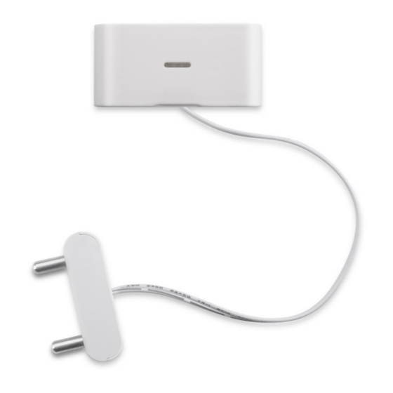
The Dragino LWL01 is a LoRaWAN Water Leak Sensor. It detects the water leak status and send it to LoRaWAN network. The LWL01 is small sensor, the dimension is as small as 64 x 30 x 14 mm. LWL01 is powered by a CR2032 coin battery, in a good LoRaWAN Network Coverage case, it can transmit as many as 12,000 uplink packets (base on SF7, 14dB). -
Page 4: Features
Logistics and Supply Chain Management Smart Metering Smart Agriculture Smart Cities Smart Factory 1.4 Dimension 1.5 Firmware Change log LWL01 Image files – Download link Image v1.0 Release LoRaWAN Water Leak User Manual 4 / 14... -
Page 5: Power On Lwl01
2. Power ON LWL01 When receive the LWL01, please open the enclosure and remove the isolated paper and PRESS RESET so the coin battery can power on the device and device runs in low power mode. The will blink when devices is powered. -
Page 6: Operation Mode
Here shows an example for how to join the TTN Network. Below is the network structure, we use our LG308 as LoRaWAN gateway here. The LWL01 in installed on the door edge to detect the open / close event. And send the status to LoRaWAN server. The LWL01 will uplink two type of messages to the server. -
Page 7: Uplink Payload
Add APP KEY and DEV EUI Step 2: Power on LWL01 and it will auto join to the TTN network. After join success, it will start to upload message to TTN and user can see in the panel. 3.3 Uplink Payload... -
Page 8: Downlink Payload
Clear Counting 0xA6 Example Downlink payload setting in TTN: Type Code 0x01 If the payload=0100003C, means to control the LWL01’s Keep Alive interval to 0x00003C=60(S) Type Code 0x04 If payload = 0x04FF, it will reset the LWL01. Type Code 0xA6 Example: 0xA601: Clear Counting For LWL01: reset count number. -
Page 9: Integrate With Mydevice
3.5 Integrate with Mydevice Mydevices provides a human friendly interface to show the sensor data, once we have data in TTN, we can use Mydevices to connect to TTN and see the data in Mydevices. Below are the steps: Step 1: Be sure that your device is programmed and properly connected to the network at this time. -
Page 10: Leds
Step 3: Create an account or log in Mydevices. Step 4: Search LWL01 and add DevEUI. 3.6 LEDs Action LED behavior Power On GREEN on 1s, on 1s, BLUE on 1s Joined successful GRENN LED on 5s Send an uplink message... - Page 11 LWL01 is powered by a CR2032 coin battery, when running in deep sleep mode, the device power consumption is ~5uA. The main power consumption is transmitting an uplink message. Depends on LoRaWAN network signal strength, the device can send different number of uplink messages.
-
Page 12: Use At Command
4. Use AT Command 4.1 Access AT Command LWL01 supports AT Command set. User can use a USB to TTL adapter to configure LWL01 via use AT command, as below. USB to TTL <- -> LWL01 RX <- -> TX TX <- ->... -
Page 13: Faq
5. FAQ 5.1 How to upgrade the image? User can upgrade the firmware of LWL01 for bug fix, new features, or change working region. The upgrade instruction are here: http://wiki.dragino.com/index.php?title=Firmware_Upgrade_Instruction 5.2 How to change the LoRa Frequency Bands/Region? User can follow the introduction for how to upgrade image. -
Page 14: Order Info
US915: frequency bands US915 IN865: frequency bands IN865 CN779: frequency bands CN779 7. Packing Info Package Includes: LWL01 x 1 Dimension and weight: Device Size: 64 x 30 x 14 mm 8. Support Support is provided Monday to Friday, from 09:00 to 18:00 GMT+8. Due to different timezones we cannot offer live support.
Need help?
Do you have a question about the LWL01 and is the answer not in the manual?
Questions and answers