Table of Contents
Advertisement
Quick Links
Advertisement
Table of Contents
Troubleshooting

Related Manuals for AEC IST6


Summary of Contents for AEC IST6
- Page 1 UPS IST6 (200-600kVA) Series User Manual www.aecups.com...
- Page 2 Summaries Thank you for choosing the IST6 series modular UPS! This document gives a description of the IST6 series modular UPS, including the features, performance, appearance, structure, working principles, installation, operation and maintenance.etc. Please save the manual after reading, in order to consult in the future.
- Page 3 IST6 Series (200K-600K) Modular UPS User Manual Foreword Symbol Description Be care electric shock prompting. Provides a tip that may help you solve a problem or save time. Provides additional information to emphasize or supplement important points in the main text.
-
Page 4: Table Of Contents
IST6 Series (200K-600K) Modular UPS Contents User Manual Contents 1 Safety Description......................... 1 1.1 Safety Announcements ............................. 1 1.1.1 Safety Instructions ..........................1 1.1.2 Use Announcements for Battery ......................4 1.1.3 ESD Protection ............................5 1.1.4 Grounding Requirements ........................5 1.1.5 Warning Label Setting .......................... - Page 5 3.4.2 Optional Accessory Installation ......................42 3.5 System Wiring ..............................43 3.5.1 IST6-200,IST6-300(Bottom wiring) ....................43 3.5.2 IST6-200, IST6-300(Top wiring) ......................46 3.5.3 IST6-400, IST6-500, IST6-600 ......................50 3.6 Parallel System Connection ........................... 54 3.7 System Check and Test ........................... 57 3.7.1 Check Electrical Connection .........................
- Page 6 IST6 Series (200K-600K) Modular UPS Contents User Manual 4.3 System Work Status Display .......................... 61 4.4 Buzzer Control Function ..........................67 4.5 Monitor Function ............................68 4.5.1 Bypas Information ..........................68 4.5.2 Mains Information ..........................68 4.5.3 Battery Information ..........................69 4.5.4 Power Module Information ........................
- Page 7 IST6 Series (200K-600K) Modular UPS User Manual Contents 5.3.3 UPS Shutdown ............................95 5.3.4 Switch to Bypass Mode Manually ......................96 5.3.5 Switch to Maintenance Bypass Mode From Normal Output ..............96 5.3.6 Switch to Inverter Power Supply from Maintenance Bypass ..............97 5.3.7 Emergency Power Off(EPO) .........................
-
Page 8: Safety Description
IST6 Series (200K-600K) Modular UPS User Manual 1 Safety Description 1 Safety Description This chapter introduces the safety announcements. Prior to performing any work on the UPS, please read the user manual carefully to avoid human injury and device damage by irregular operations. - Page 9 IST6 Series (200K-600K) Modular UPS 1 Safety Description User Manual It is prohibited to touching any terminal or conductor that connected with grid circuit, or, it may cause deadly danger. The damaged device or device fault may cause electric shock or firing! ...
- Page 10 IST6 Series (200K-600K) Modular UPS User Manual 1 Safety Description Do not reversely connect the grounding wire and neutral wire, live wire and neutral wire, which will cause short circuit. It should be well grounded and the voltage between ground wire and neutral wire should be less than Please do not put finger or tool into rotating fans to avoid endanger the human safety or damage the device.
-
Page 11: Use Announcements For Battery
IST6 Series (200K-600K) Modular UPS 1 Safety Description User Manual When UPS is power off, there still exists dangerous voltage. It should affix warning labels away from UPS location and the warning labels should include: 1. It supplies power for UPS. 2. Please disconnect UPS before wiring. -
Page 12: Esd Protection
IST6 Series (200K-600K) Modular UPS User Manual 1 Safety Description 1.1.3 ESD Protection To prevent human electrostatic damaging sensitive components (such as circuit board), make sure that you wear a anti-static wrist strap before touching sensitive components, and the other end is well grounded. - Page 13 IST6 Series (200K-600K) Modular UPS 1 Safety Description User Manual The related operation and wiring for the UPS should be performed by qualified professionals, and ensure the electric installation accord with the electricity installation standards. The installation and maintenance man should be trained and know about each safety announcements and get the right operation method, and then, the installation, operation and maintenance can be done.
-
Page 14: Environment Requirements
IST6 Series (200K-600K) Modular UPS User Manual 1 Safety Description Changing the UPS configuration, structure or assembly will affect the performance of the UPS. If user needs to do like this, please consult the manufacturer in advance. 1.3 Environment Requirements Do not put the UPS in the environment where has inflammable, explosive gas or smog, do not do any operation in this environment. -
Page 15: Overview
2.1 Product Intro IST6 series UPS is modular online double-conversion UPS. They are made up of cabinet, power module, bypass module, system control box and distribution unit. The system is designed in module and user can online add /decrease or replace the power module conveniently and do not worry about the normal operation of system. - Page 16 IST6 Series (200K-600K) Modular UPS User Manual 2 Overview Energy conservation and high efficiency Adopts advanced PFC control technology, the input power factor is greater than 0.99, which greatly improves the use ratio of electric energy and reduces the load of power grid, and save the cost of power distribution.
-
Page 17: Work Principle
Figure2-1 Work principle diagram 2.3.2 Work Mode There are 4 work modes of the IST6 series modular UPS: normal mains power supply mode, battery power supply mode, bypass power supply mode and maintenance bypass power supply mode. Normal mains power supply mode When the mains normal, AC power is transformed to DC power by PFC, and supply power for inverter. - Page 18 IST6 Series (200K-600K) Modular UPS User Manual 2 Overview Battery power supply mode When mains abnormal, system will switch to battery input, the Boost circuit promotes the battery voltage to a certain value and then supply the DC power to the inverter, that makes the AC output without interruption phenomenon and then protect the load.
-
Page 19: Structure
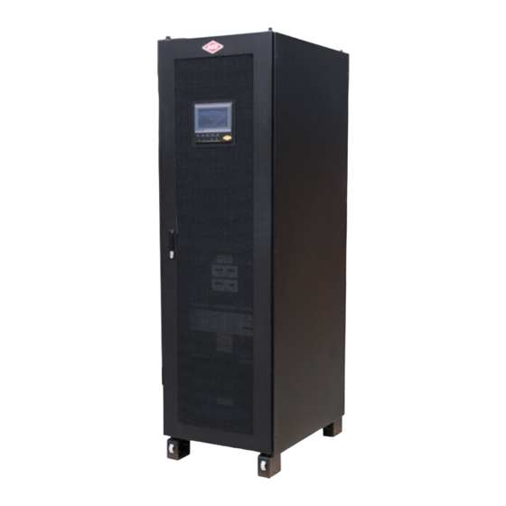
2.4 Structure IST6 series modular UPS is mainly made up of cabinet, operation panel, power module, bypass module, system control box, distribution unit, etc. The appearance of IST6 series modular UPS is as shown in Figure2-2, Figure2-3. Figure2-2 Appearance of IST6200, IST6300 Figure2-3 Appearance of IST6400, IST6500, IST6600 All rights reserved ©Allis Electric Co., Ltd. - Page 20 IST6 Series (200K-600K) Modular UPS User Manual 2 Overview Operation Panel Figure2-4 Operation panel IST6 IST6 series(200K-600K) Table2-1 Illustration for operation panel Name Illustration ○ Touch screen Human-machine interactive interface On (Green): the rectifier work normally. ○ AC/DC indicator On (Red): the rectifier work abnormally.
-
Page 21: Sturcture Layout
The system layout diagram takes the power module full allocation as an example, please refer to the real product. IST6-200, IST6-300 (Bottom wiring) Figure2-5 System layout diagram of IST6-200, IST6-300 (Bottom wiring) IST6-200, IST6-300 (Top wiring) Figure2-6 System layout diagram of IST6-200, IST6-300 (Top wiring) -
Page 22: Power Module
IST6 Series (200K-600K) Modular UPS User Manual 2 Overview IST6-400, IST6-500, IST6-600 Figure2-7 System layout diagram of IST6-400, IST6-500, IST6-600 (Open front door) 2.4.2 50kW Power Module Appearance Figure2-8 Appearance of power module All rights reserved ©Allis Electric Co., Ltd. - Page 23 IST6 Series (200K-600K) Modular UPS 2 Overview User Manual Operation panel Figure2-9 Operation panel of power module Table2-2 Illustration for the operation panel of power unit Name Illustration On: power module stay in inverter status ○ RUN indicator (Green) Flicker: power module stay in standby status.
-
Page 24: Bypass Module
IST6 Series (200K-600K) Modular UPS User Manual 2 Overview 2.4.3 Bypass Module Appearance Figure2-10 Appearance of bypass module Operation panel Figure2-11 Operation panel of bypass module Table2-3 Illustration for the operation panel of bypass unit Name Illustration ○ RUN indicator (Green) On: bypass unit is running. -
Page 25: System Control Box
IST6 Series (200K-600K) Modular UPS 2 Overview User Manual Name Illustration Place the ready switch to “unlock” status, the indication color is green, the bypass module is not locked with the cabinet, and at this time, the bypass module can be ○... - Page 26 IST6 Series (200K-600K) Modular UPS User Manual 2 Overview Name Illustration system to synchronize the output frequency and phase position of each system, which is to ensure the two bus can switch each other. Parallel signal port. When several UPS used in parallel system, it needs to use the parallel control wire to connect the parallel port of each UPS in ringlike.
- Page 27 ○ port communication. RS232 port adopts RJ45 plug. The pin definition of RS232 port is shown in Figure2-15. he communication protocol supports MODBUS RTU or AEC MODBUS/RS485 standard serial port protocol, which can be switched by touch ○ communication port screen.
- Page 28 IST6 Series (200K-600K) Modular UPS User Manual 2 Overview 1--8 RJ45 RJ45 plug Pin definition: Pin 1:White orange-Reserved 1 2 3 4 5 6 7 8 Pin 2:Orange-Reserved Pin 3:White green-MODBUS:A Pin 4:Blue-MODBUS:B 1 2 3 4 5 6 7 8 Pin 5:White blue-MODBUS:A...
-
Page 29: Optional Accessory
2.5 Optional Accessory The IST6 series modular UPS can be equipped with different accessories to meet the needs of different users. 2.5.1 SNMP Card and Its Software SNMP card(As shown in Figure2-17) is installed in the UPS to realize the UPS remote management. - Page 30 IST6 Series (200K-600K) Modular UPS User Manual 2 Overview Table2-8 Illustration for SNMP card Name Function description ○ Indicator Show working status ○ COM1 port Connect with humiture module(RS485) ○ NETWORK port Ethernet port Table2-9 Illustration for indicator Green indicator (R)
- Page 31 IST6 Series (200K-600K) Modular UPS 2 Overview User Manual SNMP card software It is suitable but not only for the following browsers(the early operating system may not be good in compatibility): Chrome56+ browser, IE11+ browser. The login interface is different in different browser.
-
Page 32: Parallel System Connection
IST6 Series (200K-600K) Modular UPS User Manual 2 Overview ----End 2.5.2 Parallel System Connection Parallel wires are for parallel ports connection between cabinets. When multi UPSs in parallel, connect the parallel port of each UPS by parallel wire. N UPSs require N parallel wires to ensure there are at least two parallel wires for a UPS, which will improve parallel reliability. -
Page 33: Surge Protection Device
In areas where lightning strikes are frequent, multistage surge protection system should be installed at the incoming wire of the mains to ensure the safe operation of the device. IST6 series UPS can be equipped with a Class C SPD. - Page 34 IST6 Series (200K-600K) Modular UPS User Manual 2 Overview Alarm action Protection action Fault name Battery over-voltage It is not allowed to supply power by battery or charge battery Battery circuit abnormal Buzzer beeps apace None Battery backup time is not enough.
- Page 35 IST6 Series (200K-600K) Modular UPS 2 Overview User Manual Alarm action Protection action Fault name Battery low-temperature alarm. PFC software version is inconformity. INV software version is inconformity. System control card X- software version is inconformity. The static startup is not allowed.
- Page 36 IST6 Series (200K-600K) Modular UPS User Manual 2 Overview Alarm action Protection action Fault name large. It turns to float charge. The charge current-limiting value will Battery high-temperature alarm. be set to 0.05C Charging is not allowed. Battery over-temperature. After the protection for battery under-voltage, once mains recover to normal power supply, the UPS will restart and charge the batteries.
-
Page 37: Installation
The UPS installation should be performed by authorized person who is special trained and achieve the qualification of high-voltage and AC power. The UPS is just suitable for installing on the concrete or nonflammable surface. 3.1 Installation Process The installation process of IST6 series modular UPS is as shown in Figure3-1. Start Installation preparation... -
Page 38: Installation Preparation
IST6 Series (200K-600K) Modular UPS User Manual 3 Installation 3.2 Installation Preparation 3.2.1 Installation Tools Tools All rights reserved ©Allis Electric Co., Ltd. -
Page 39: Installation Environment
IST6 Series (200K-600K) Modular UPS 3 Installation User Manual The installation tools should be with isolated operation to avoid electric shock. 3.2.2 Installation Environment Do not install the UPS in the place where exceeds the provision of technology index (temperature: 0℃~40℃, relative humidity: 0%~95%). -
Page 40: Installation Space
IST6 Series (200K-600K) Modular UPS User Manual 3 Installation 3.2.3 Installation Space Maintain a clearance of at least 800mm from the front panel or rear panel of the UPS to the wall or adjacent device, and maintain a clearance of at least 500mm from the top of the UPS to ceiling, which is to ensure good ventilation, as shown in Figure3-2. - Page 41 IST6 Series (200K-600K) Modular UPS 3 Installation User Manual Table3-1 Recommended wire and terminal specification (The power of single power module is 50kVA) Model System max. capacity (kVA) AC input current (A) 1045 Recommended 2×(4 2×(4× 2×(4× 2×(4× 3×(4× wire diameter U/V/W/N ×95)
-
Page 42: Surge Protection Device
IST6 Series (200K-600K) Modular UPS User Manual 3 Installation Model System max. capacity (kVA) 2×(3 2×(3× 2×(3× 3×(3× 3×(3× Recommended wire +/N/- ×120) diameter (mm 120) 150) 185) 240) Wire terminal model DT-120 DT-120 DT-150 DT-185 DT-240 Recommended wire diameter (mm... - Page 43 IST6 Series (200K-600K) Modular UPS 3 Installation User Manual The UPS should be transported by trained professional. During transporting, please take care and avoid impact or falling off. If the UPS needs to be stored for a long time after unpacking, it is suggested to package the UPS with original plastic bag.
-
Page 44: Unpacking
Compare with the packing list and check if the accessories mode is complete and proper. If the accessories lack or model wrong, please take note and contact the AEC Company or local agency of our company. -
Page 45: Mechanical Installation
IST6 Series (200K-600K) Modular UPS 3 Installation User Manual Step 6 Unscrew the bolts that connected with cabinet and wooden bracket by socket wrench, the bolt position is as shown in Figure3-6. Figure3-6 Bolt position ----End 3.4 Mechanical Installation 3.4.1 UPS Installation In this section, we take ground installation as an example to illustrate. - Page 46 IST6 Series (200K-600K) Modular UPS User Manual 3 Installation The wiring groove requirements of IST6 series UPS is the same, in above figure, we take IST6400 as an example to illustrate. The recommended wiring groove size is as follows: for IST6200, IST6300A×D×H:650×200×...
- Page 47 If the UPS is installed on U-steel, drill 4 hole (hole diameter isφ14) on the U-steel directly, and then perform Step 4 directly. Figure3-10 Bottom size of IST6-200, IST6-300 (unit: mm) Figure3-11 Bottom size of IST6400, IST6500, IST6600 (unit: mm) Step 3 Install expansion bolts.
- Page 48 IST6 Series (200K-600K) Modular UPS User Manual 3 Installation Bolt 1. Drill holes on the installation ground by hammer drill. Spring gasket Flat gasket 2. Tighten The expansion bolts mildly, and put it to the hole vertically, and then knock the expansion bolt by rubber hammer till all the expansion tube into the hole.
-
Page 49: Optional Accessory Installation
IST6 Series (200K-600K) Modular UPS 3 Installation User Manual Figure3-13 Install bottom cover plates of IST6400, IST6500, IST6600 ----End 3.4.2 Optional Accessory Installation The SNMP card is a independent product. Install it in the installation position. Step 1 Dismantle the SNMP card plate on the system control box, as shown in Figure3-14. -
Page 50: System Wiring
IST6 Series (200K-600K) Modular UPS User Manual 3 Installation Step 3 Connect the IN port of SNMP card with the RS232 port of system monitor card through the equipped with network wire, as shown in Figure3-16. PARALLEL NORMAL B-Temp EPO1... - Page 51 IST6 Series (200K-600K) Modular UPS 3 Installation User Manual Figure3-17 is as an example. The module number please refers to the product. Step 2 Draw the input wires, output wires, battery wires through the bottom holes(As shown in Figure3-18), and connect them to the corresponding copper bar(As shown in Figure3-19 and Figure3-20), and fasten the bolts.
- Page 52 IST6 Series (200K-600K) Modular UPS User Manual 3 Installation Figure3-20 Wiring terminal 2 When the mains and bypass are with the same input source, it should connect the input copper bars with bypass copper bars through equipped copper bars, as shown in Figure3-21.
-
Page 53: Ist6200, Ist6300(Top Wiring)
IST6 Series (200K-600K) Modular UPS 3 Installation User Manual Figure3-22 Battery wire connection diagram Step 3 After finishing the wire connection, install the bottom wiring cover plate and fill the empty party with insulation fireproofing mud, then the wiring is completed. - Page 54 IST6 Series (200K-600K) Modular UPS User Manual 3 Installation Figure3-24 Remove the sealing plate diagram Step 2 Draw the input wires, output wires, battery wires through the top holes(As shown in Figure3-25), and connect them to the corresponding copper bar(As shown in Figure3-26 and Figure3-29), and fasten the bolts.
- Page 55 IST6 Series (200K-600K) Modular UPS 3 Installation User Manual Figure3-26 Wiring diagram 1 Figure3-27 Wiring diagram 2 When the mains and bypass are with the same input source, it should connect the input copper bars with bypass copper bars through equipped copper bars, as shown in Figure3-28.
- Page 56 IST6 Series (200K-600K) Modular UPS User Manual 3 Installation Figure3-28 Connection diagram for the mains and bypass with the same input source It is suggested to equip DC breaker for battery DC input, specific wire connection is as shown in Figure3-29.
-
Page 57: Ist6400, Ist6500, Ist6600
IST6 Series (200K-600K) Modular UPS 3 Installation User Manual Figure3-30 Wiring diagram of IST6200, IST6300 When the mains and bypass are with the same input source, the bypass copper bar doesn't need to be wired. ----End 3.5.3 IST6400, IST6500, IST6600... - Page 58 IST6 Series (200K-600K) Modular UPS User Manual 3 Installation Figure3-32 Dismantle the wiring cover plate of distribution cabinet Step 3 Connect the input wires, output wires and battery wires according to Figure3-33 in proper order, and then fasten the bolts.
- Page 59 IST6 Series (200K-600K) Modular UPS 3 Installation User Manual If the wiring is from upside, it needs to make the cable go through the top styrofoam, and then connect the cables. If the wiring is form downside, it needs to knock down the bottom wiring hole, and then connect the cables.
- Page 60 IST6 Series (200K-600K) Modular UPS User Manual 3 Installation Figure3-35 Wiring diagram of distribution cabinet(Top wiring) Figure3-36 Wiring diagram of distribution cabinet(Bottom wiring) Step 5 After finish the installation of cover plate, fill the empty part with insulation fireproofing mud.
-
Page 61: Parallel System Connection
IST6 Series (200K-600K) Modular UPS 3 Installation User Manual ----End After finish the assembling, perform the test and then the UPS can be put in use. 3.6 Parallel System Connection When the wiring of parallel system is needed, please refer to Figure3-37, Figure3-38 to connect the parallel system. - Page 62 IST6 Series (200K-600K) Modular UPS User Manual 3 Installation Parallel system connection of IST6200, IST6300(Top wiring) Figure3-39 Parallel system connection diagram of IST6200, IST6300(Top wiring) The wire color above is just used to distinguish the different ports, the actual wire color may not be the same as shown in the figure’s.
- Page 63 IST6 Series (200K-600K) Modular UPS 3 Installation User Manual The wire color above is just used to distinguish the different ports, the actual wire color may not be the same as shown in the figure’s. Parallel system connection of IST6400, IST6500, IST6600 Figure3-41 Parallel system connection diagram of IST6400、IST6500、IST6600(Top wiring)
-
Page 64: System Check And Test
IST6 Series (200K-600K) Modular UPS User Manual 3 Installation The wire color above is just used to distinguish the different ports, the actual wire color may not be the same as shown in the figure’s. 3.7 System Check and Test 3.7.1 Check Electrical Connection... -
Page 65: Connect Load
IST6 Series (200K-600K) Modular UPS 3 Installation User Manual 3.7.3 Connect Load After the UPS starting and working stably, turn on the load. Start big-power devices before small-power ones. Some devices has large starting current which may cause overload protection (or bypass operation), it is better to start these equipment before others. -
Page 66: Touch Screen Operation And Setting
IST6 Series (200K-600K) Modular UPS User Manual 4 Touch Screen Operation and Setting 4 Touch Screen Operation and Setting This chapter mainly introduces the work parameters and work status and system setting of the UPS. 4.1 Menu Structure Mains input... -
Page 67: Main Page
IST6 Series (200K-600K) Modular UPS 4 Touch Screen Operation and Setting User Manual The value in the figures of this chapter is just for illustration, for real page please see the actual achieved product. 4.2 Main Page After powering on, it will enter system monitor main page, as shown in Figure4-2. -
Page 68: System Work Status Display
IST6 Series (200K-600K) Modular UPS User Manual 4 Touch Screen Operation and Setting : Information record. : System parameter setting. : Login. : Buzzer control. : Alarm. : ON/OFF. The work status and energy flow on the main page shows the system running status and module running condition directly. - Page 69 IST6 Series (200K-600K) Modular UPS 4 Touch Screen Operation and Setting User Manual Figure4-4 Fault protection, with no output Figure4-5 Shutdown All rights reserved ©Allis Electric Co., Ltd.
- Page 70 IST6 Series (200K-600K) Modular UPS User Manual 4 Touch Screen Operation and Setting Figure4-6 Exit parallel system Figure4-7 Bypass output All rights reserved ©Allis Electric Co., Ltd.
- Page 71 IST6 Series (200K-600K) Modular UPS 4 Touch Screen Operation and Setting User Manual Figure4-8 Battery INV. output Figure4-9 Mains INV. output All rights reserved ©Allis Electric Co., Ltd.
- Page 72 IST6 Series (200K-600K) Modular UPS User Manual 4 Touch Screen Operation and Setting Figure4-10 Grid-connected aging running Figure4-11 ECO bypass output All rights reserved ©Allis Electric Co., Ltd.
- Page 73 IST6 Series (200K-600K) Modular UPS 4 Touch Screen Operation and Setting User Manual Figure4-12 Frequency conversion INV. output Figure4-13 Maintenance bypass output All rights reserved ©Allis Electric Co., Ltd.
-
Page 74: Buzzer Control Function
IST6 Series (200K-600K) Modular UPS User Manual 4 Touch Screen Operation and Setting Figure4-14 Aging bypass output When module or system abnormal, the main page will show “fault alarm” indicator, click the “fault alarm”, it will show the current fault information, as shown in Figure4-15. -
Page 75: Monitor Function
IST6 Series (200K-600K) Modular UPS 4 Touch Screen Operation and Setting User Manual 4.5 Monitor Function 4.5.1 Bypas Information In main page, click icon, it will enter system bypass information page, as shown in Figure4-16. In the page, it shows the bypass three-phase voltage, current, active power, apparent power and frequency. -
Page 76: Battery Information
IST6 Series (200K-600K) Modular UPS User Manual 4 Touch Screen Operation and Setting Figure4-17 Mains information 4.5.3 Battery Information In main page, click icon, it will enter battery information page. If the battery is lead-acid cell, it shows the positive and negative battery group voltage, charge/discharge current, remaining capacity, battery remaining time, battery temperature, battery status. -
Page 77: Power Module Information
IST6 Series (200K-600K) Modular UPS 4 Touch Screen Operation and Setting User Manual code, SOC, SOH and battery status. It shows the charging current or discharging current according to battery charge/discharge status, as shown in Figure4-19. Figure4-19 Battery information page 4.5.4 Power Module Information... -
Page 78: Inverter Information
IST6 Series (200K-600K) Modular UPS User Manual 4 Touch Screen Operation and Setting 4.5.5 Inverter Information In main page, click icon, it will enter inverter module information page, as shown in Figure4-21. Click “Select Module”, it can check the information of each power module. -
Page 79: Setting Management
IST6 Series (200K-600K) Modular UPS 4 Touch Screen Operation and Setting User Manual 4.6 Setting Management In main page, click icon, it will enter user login page, as shown in Figure4-23. Figure4-23 Use login page After entering right password the icon will show as . -
Page 80: System Manage
IST6 Series (200K-600K) Modular UPS User Manual 4 Touch Screen Operation and Setting 4.6.1 System Manage In setting management interface, click System Manage icon, it will enter system manage page, as shown in Figure4-25. System manage includes system setting, bypass setting. Click enter box to change parameter. - Page 81 IST6 Series (200K-600K) Modular UPS 4 Touch Screen Operation and Setting User Manual Figure4-27 Setting failure Bypass setting Click Bypass Setting, it will turn to bypass setting page, as shown in Figure4-28. Click enter box, such as the max. time turn INV. to bypass synchronous (ms), it will show as Figure4-29. At the top of the enter box, it shows the setting range, once setting exceed the range, the setting will be invalid, after change the parameter, click Save button to save the setting.
-
Page 82: Battery Manage
IST6 Series (200K-600K) Modular UPS User Manual 4 Touch Screen Operation and Setting Figure4-29 Parameter setting 4.6.2 Battery Manage In setting management page, click Battery Manage icon, it will enter battery manage page, as shown in Figure4-30, Figure4-31.The page includes battery setting, charging setting, battery test. Click enter box to change the parameter. - Page 83 IST6 Series (200K-600K) Modular UPS 4 Touch Screen Operation and Setting User Manual Figure4-31 Battery setting 2 Charging setting Click Charging Setting, it will turn to charging setting page, as shown in Figure4-32, Figure4-33. Click enter box to change the parameter. Click Save button to save the setting. The mark of setting success and setting failure is the same as that of system setting.
-
Page 84: Mode Configuration
IST6 Series (200K-600K) Modular UPS User Manual 4 Touch Screen Operation and Setting Figure4-33 Charging setting 2 Battery test Click Battery Test to enter battery test page, as shown in Figure4-34. Figure4-34 Battery test 4.6.3 Mode Configuration In setting management page, click Mode config. icon, it will enter mode configuration page. The page includes parallel configuration, ECO configuration, smart sleep setting and other mode setting. - Page 85 IST6 Series (200K-600K) Modular UPS 4 Touch Screen Operation and Setting User Manual Figure4-35 Parallel configuration page Click ECO Setting, it will turn to ECO configuration page, as shown in Figure4-36. Click enter box to change the setting. Click Save button to save the setting. The mark of setting success and setting failure is the same as that of system setting.
-
Page 86: Function Configuration
IST6 Series (200K-600K) Modular UPS User Manual 4 Touch Screen Operation and Setting Figure4-37 Smart sleep setting page Click Other Mode Setting, it will turn to other mode setting page, as shown in Figure4-38. Click enter box to change the setting. Click Save button to save the setting. The mark of setting success and setting failure is the same as that of system setting. - Page 87 IST6 Series (200K-600K) Modular UPS 4 Touch Screen Operation and Setting User Manual point configuration. Click Save button to save the setting. The mark of setting success and setting failure is the same as that of system setting. Generator configuration In funciton configuration page, click Generator, it will enter the generator configuration page, as shown in Figure4-39.
- Page 88 IST6 Series (200K-600K) Modular UPS User Manual 4 Touch Screen Operation and Setting Figure4-40 Dedusting configuration Start delay configuration Click StartDelay, it will enter the delay starting configuration page, as shown in Figure4-41. Click Save button to save the setting. The mark of setting success and setting failure is the same as that of system setting.
-
Page 89: Communication Setting
IST6 Series (200K-600K) Modular UPS 4 Touch Screen Operation and Setting User Manual Dry point configuration Click Dry point, it will enter the dry contact configuration page, as shown in Figure4-42. Click Save button to save the setting. The mark of setting success and setting failure is the same as that of system setting. -
Page 90: Debug Set
IST6 Series (200K-600K) Modular UPS User Manual 4 Touch Screen Operation and Setting Figure4-43 Communication setting 4.6.6 Debug Set In setting management page, click Debug Set icon, it will enter debug set page, as shown in Figure4-44. Click Save button to save the setting. The mark of setting success and setting failure is the same as that of system setting. -
Page 91: Record Manage
IST6 Series (200K-600K) Modular UPS 4 Touch Screen Operation and Setting User Manual 4.6.7 Record Manage In setting management page, click Record Manage icon, it will enter record manage page, as shown in Figure4-45, Figure4-46. Click Save button to save the setting. The mark of setting success and setting failure is the same as that of system setting. -
Page 92: Password Set
IST6 Series (200K-600K) Modular UPS User Manual 4 Touch Screen Operation and Setting Figure4-47 HMI setting When setting system time, ensure that the setting value is the same as the real time, which is to keep the veracity of system event log and master the system status of some time and maintain conveniently. -
Page 93: Information Query
IST6 Series (200K-600K) Modular UPS 4 Touch Screen Operation and Setting User Manual Figure4-48 Password setting 4.7 Information Query In main page, click icon, it will enter information query page, as shown in Figure4-49. Figure4-49 Information query All rights reserved ©Allis Electric Co., Ltd. -
Page 94: Event Log
IST6 Series (200K-600K) Modular UPS User Manual 4 Touch Screen Operation and Setting It can record 9000 pieces information at most. When the record exceeds 9000 piece, the earliest information will be covered by new one. All records are ranked in inverted order of time. -
Page 95: Device Information
IST6 Series (200K-600K) Modular UPS 4 Touch Screen Operation and Setting User Manual Figure4-51 User log 4.7.3 Device Information In information query page, click Device Info icon, it will enter device information page. This page shows the S/N, product name, model, status, version, as shown in Figure4-52, Figure4-53, Figure4-54. - Page 96 IST6 Series (200K-600K) Modular UPS User Manual 4 Touch Screen Operation and Setting Figure4-53 Product information 2 Figure4-54 Product information 3 When the probation function is enabled, the device status shows as Lock, as shown in Figure4-55. At this time, click Lock button, it will enter the probation unlock page. After unlocking, the Lock button disappear.
-
Page 97: On/Off
IST6 Series (200K-600K) Modular UPS 4 Touch Screen Operation and Setting User Manual Figure4-55 Probation function is enabled 4.8 ON/OFF In main page, click icon, it will enter ON/OFF page, when the system is OFF, click the icon to enter the confirm page, as shown in Figure4-56, click OK button to perform the start operation. - Page 98 IST6 Series (200K-600K) Modular UPS User Manual 4 Touch Screen Operation and Setting Figure4-57 Confirm to power off All rights reserved ©Allis Electric Co., Ltd.
-
Page 99: Use And Operation
IST6 Series (200K-600K) Modular UPS 5 Use and Operation User Manual 5 Use and Operation This chapter mainly introduces the operation procedure and method, including using announcements, operation procedure, UPS start and parallel system start, etc. 5.1 Use Announcements Before starting the UPS, check whether the load is proper. The load must not exceed the rated output power of the UPS, which is to avoid overload protection. -
Page 100: Ups Start And Shutdown
IST6 Series (200K-600K) Modular UPS User Manual 5 Use and Operation 5.3 UPS Start and Shutdown 5.3.1 Check before Startup Before startup, check according to following steps. Only when the check is OK, then the UPS can be started. Step 1 Ensure that the POWER switch, BYPASS switch, OUTPUT switch, MAINTENANCE switch are all OFF. - Page 101 IST6 Series (200K-600K) Modular UPS 5 Use and Operation User Manual Start the inverter by panel ON combination button 1 When the green indicator of all power module slow flicker, long press the panel “ON” combination button for 3s, the system inverters to output. Check the system running status in the touch screen, and ensure that the system turns to inverter power supply mode.
-
Page 102: Ups Shutdown
IST6 Series (200K-600K) Modular UPS User Manual 5 Use and Operation 5.3.3 UPS Shutdown If the system bypass normal, after the UPS shutdown, system will turn to bypass power supply mode; if system bypass abnormal, after the UPS shutdown, system will be with no output. Before shutting down, please ensure that the load is closed. -
Page 103: Switch To Bypass Mode Manually
IST6 Series (200K-600K) Modular UPS 5 Use and Operation User Manual Step 4 After the touch screen and all LED indicators are off, the UPS is completely shut down. ----End 5.3.4 Switch to Bypass Mode Manually Before shutting down the inverter, please ensure that the bypass is normal. If bypass abnormal, after shutting down the inverter manually, the system will be with no output and the power supply for load will be broken off. -
Page 104: Switch To Inverter Power Supply From Maintenance Bypass
IST6 Series (200K-600K) Modular UPS User Manual 5 Use and Operation Step 4 Disconnect OUTPUT switch, after the touch screen, LED indicators are all off, the maintenance can be done. Disconnect external OUTPUT switch, after the touch screen, LED indicators are all off, the maintenance can be done. -
Page 105: Emergency Power Off(Epo)
IST6 Series (200K-600K) Modular UPS 5 Use and Operation User Manual 5.3.7 Emergency Power Off(EPO) Do not perform the EPO operation unless emergency. Press the EPO button on the panel or external EPO button of system, the UPS will turn to emergency power off status. - Page 106 IST6 Series (200K-600K) Modular UPS User Manual 5 Use and Operation 1. Before start the parallel system, please perform the operation of 5.3 UPS Start and Shutdown for each UPS. 2. Before test and power on the parallel system, please ensure that the wire connection of input and output cables and phase sequence is right and the parallel wire is well connected and stay in disconnection status.
- Page 107 IST6 Series (200K-600K) Modular UPS 5 Use and Operation User Manual output distribution cabinet or external output distribution breaker, ensure that the inverter output voltage is normal (the three-phase output voltage = output voltage setting ±2V), and ensure that the inverter frequency is normal (the three-phase output frequency = output frequency setting ±0.1Hz).
-
Page 108: Shutdown Parallel System
IST6 Series (200K-600K) Modular UPS User Manual 5 Use and Operation Ensure that each UPS with no abnormal alarm, shut down the inverter of all UPS, the system turns to bypass power supply. Step 14 Close the total output breaker of load. -
Page 109: Emergency Power Off(Epo)
IST6 Series (200K-600K) Modular UPS 5 Use and Operation User Manual 5.4.3 Emergency Power Off(EPO) Single UPS running Press the EPO button of the UPS or the EPO button of total system, the UPS will shut down and close all output. -
Page 110: Maintenance And Troubleshooting
IST6 Series (200K-600K) Modular UPS User Manual 6 Maintenance and Troubleshooting 6 Maintenance and Troubleshooting This chapter mainly introduces the UPS maintenance guide, battery daily maintenance, battery replacement announcement and troubleshooting, etc. 6.1 Maintenance Guide Proper maintenance is the key to make the device operate in best status and with a longer service life. -
Page 111: Battery Maintenance
IST6 Series (200K-600K) Modular UPS 6 Maintenance and Troubleshooting User Manual Check the UPS status periodically and ensure that any fault can be found in time. 6.2 Battery Maintenance Battery charge requirements − When first use the battery, please start the UPS and charge the battery for 24h. during charging, the UPS still can be used, but if power outage occurs at the same time, the battery discharge time may less than the standard vale this time. -
Page 112: Troubleshooting
IST6 Series (200K-600K) Modular UPS User Manual 6 Maintenance and Troubleshooting A new battery should be with the same capacity, model, and manufacturer as the replaced one. The battery with different capacity, different type and different manufacturer battery is strictly forbidden to use together. - Page 113 IST6 Series (200K-600K) Modular UPS 6 Maintenance and Troubleshooting User Manual NO. Abnormal phenomena Possible reason 1. The UPS is serious overload or the output circuit is short-circuit. It is necessary to reduce load to proper capacity or find the reason of short-circuit. Common reason is output...
-
Page 114: Emergency Dispose For System Fault
IST6 Series (200K-600K) Modular UPS User Manual 6 Maintenance and Troubleshooting NO. Abnormal phenomena Possible reason Buzzer long beeps, the UPS turns to bypass See the fault information on touch screen. supply power. There is mains, but The mains voltage or frequency exceed the allowable range of buzzer beeps the UPS. -
Page 115: Package, Transportation And Storage
And also, the device model is printed on the package. At front of the package AEC the LOGO of AEC Company and device name is printed. -
Page 116: A Technical Specifications
IST6 Series (200K-600K) Modular UPS User Manual A Technical Specifications Technical Specifications Model IST6200 IST6300 IST6400 IST6500 IST6600 Index 3φ4W+PE Input mode Rated input voltage 220/230/240(Phase voltage) (VAC) Vin=176Vac~280Vac, it does not need to decrease rated power to use Input voltage range... - Page 117 IST6 Series (200K-600K) Modular UPS A Technical Specifications User Manual Model IST6200 IST6300 IST6400 IST6500 IST6600 Index 3φ4W+PE Output mode Output wave-form Sine-wave L-N: 220/230/240 Voltage (Vac) L—L: 380/400/415 When mains normal, it tracks the bypass input frequency; Frequency (Hz) When mains abnormal, it tracks the frequency 50±0.2% or 60±0.2% of...
- Page 118 IST6 Series (200K-600K) Modular UPS User Manual A Technical Specifications Model IST6200 IST6300 IST6400 IST6500 IST6600 Index DC startup function Equipped Three-phase input voltage, input frequency, three-phase output voltage, Touch screen display load, battery voltage, battery charge/discharge current, output current of each module and inner temperature, parameter setting, history record, etc.
-
Page 119: B Physics Characters
IST6 Series (200K-600K) Modular UPS B Physics Characters User Manual Physics Characters Physics Characters Model IST6200 IST6300 Item Optional top wiring or bottom wiring (It Optional top wiring or bottom Wiring way cannot be changed in site) wiring (It cannot be changed in site) - Page 120 IST6 Series (200K-600K) Modular UPS User Manual B Physics Characters Physics Characters Model IST6400 IST6500 IST6600 Item Compatible with top Compatible with top Compatible with top wiring Wiring way wiring and bottom wiring wiring and bottom wiring and bottom wiring...
-
Page 121: C Acronyms And Abbreviations
IST6 Series (200K-600K) Modular UPS C Acronyms and Abbreviations User Manual Acronyms and Abbreviations Alternating Current Direct Current Digital Signal Processor Energy Control Operation Emergency Power Off Light-emitting Diode Protective Earthing All rights reserved ©Allis Electric Co., Ltd. - Page 122 IST6 Series (200K-600K) Modular UPS User Manual C Acronyms and Abbreviations RS232 Recommend Standard 232 Recommend Standard 485 RS485 SNMP Simple Network Management Protocol THDv Total Harmonic Distortion of output voltage Uninterruptible Power System All rights reserved ©Allis Electric Co., Ltd.
Need help?
Do you have a question about the IST6 and is the answer not in the manual?
Questions and answers